10.
WIRING FOR 2 STAGE NITROUS SYSTEM
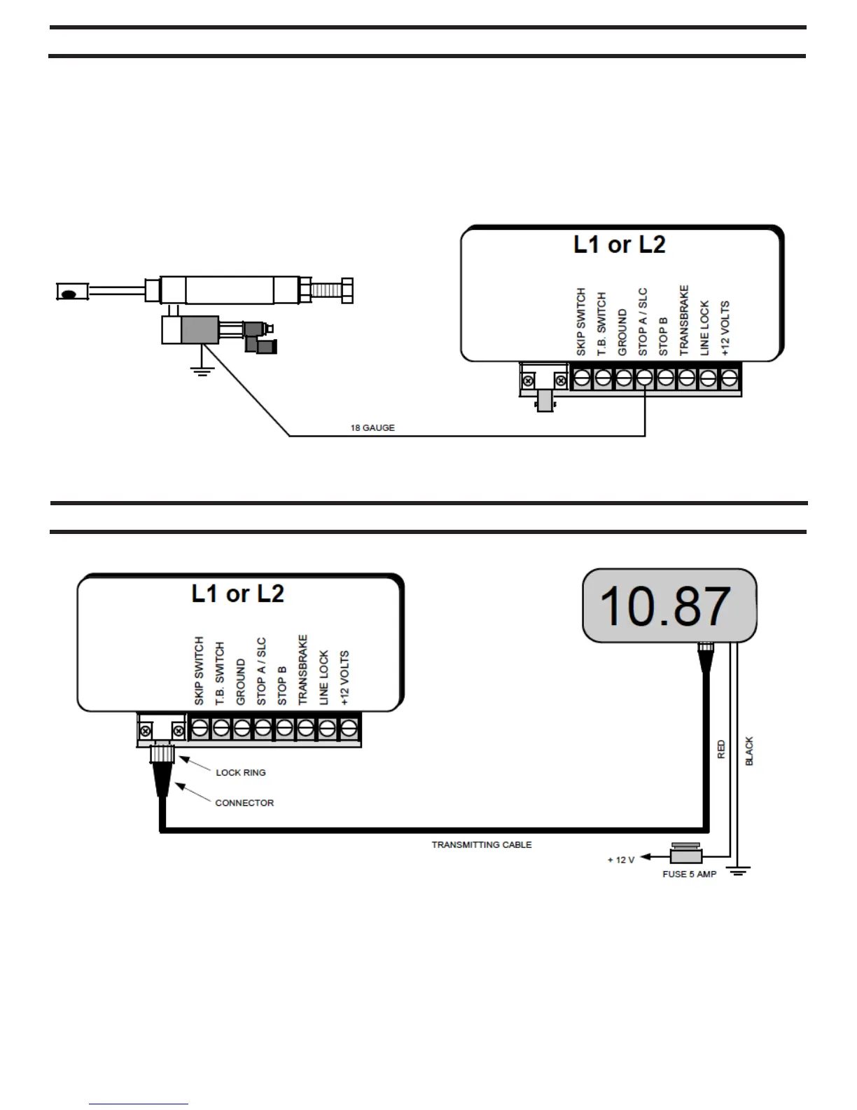
WIRING FOR REMOTE DISPLAY
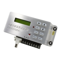
There are 3 different ways to use a linkage style throttle stop. They are wired the same.
1. Starting Line Control: In this application the linkage stop closes on the starting line when the transbrake is applied (or prior to staging if
the pre-stage feature is activated). This is to control the staging RPM of the engine. See page 6 for a complete description of starting
line control options. To use the STOP A/SLC output only as a Starting Line Control, turn the T-Stop A Control to OFF (see page 5).
2. Down Track E.T. Control: In this application the linkage stop is used only during the pass to control the vehicle’s elapsed time. Typically
racers will close the throttle stop a fraction of a second into the pass and reopen the throttle a few seconds later to slow a car for a
particular index. To use the STOP A/SLC output only as a Down Track E.T. Control, turn the Start Line Control to OFF (see page 6).
3. Both Starting Line & Down Track Control: This last application allows a racer to use the linkage stop for controlling staging RPM and
again during the pass to control the E.T
Wire the Remote Display unit as shown. Use at least 18 gauge wire connecting the black wire to a solid chassis ground and the red to +
12 volts. Use a 5 amp fuse in the red wire to protect the Remote Display from damage. Connect the display to your LIGHTNING using the
transmitting cable included with the display unit. Slip the connectors into the jacks and turn the lock ring clockwise to lock in place.
The display unit needs no set up, just power both units up and the Remote Display will show whatever is dialed in to “YOUR E.T.” setting of
the LIGHTNING. When you make a change to “YOUR E.T.” setting in the LIGHTNING and the box returns to the run mode, the Remote
Display will change accordingly.
 Loading...