2. Test procedure
2.1 The PM 20 tester may only be switched on as soon as the contacting of the protective device
to be tested is completed according to the specifications of the evaluation table (Pin assignment).
2.2 If the Test button is briefly pressed, measurement is started. Finally, the measurement result
is saved automatically in the display and the test voltage is switched off. The results of all
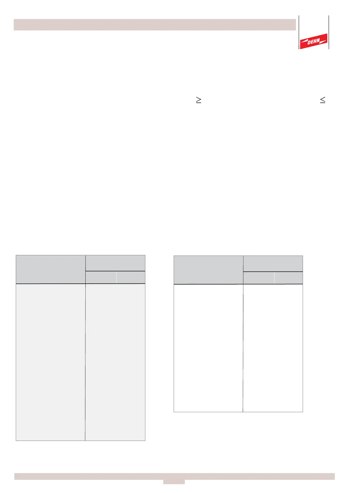
measurements for a protective module have to be
the lower limit value (LLV [V]) and
the upper limit value (ULV [V]) (see relevant evaluation table, pages 23 to 28).
2.3 Measurement is carried out considering test procedure/commissioning(see page 30).
3. Protection against contact
For safety reasons, the PM 20 tester has to be switched off before connecting/disconnecting
a device under test! The PM 20 tester has also to be switched off when reconnecting a
device under test at a protective device to be tested!
DEHNguard
Type Part No.
DG 275 900 600 386 474
DG 600 900 601 869 1063
DG 385 900 602 557 683
DG 150 900 603 215 265
DG 75 900 604 107 133
DG 320 900 605 458 562
DG 440 900 607 643 787
DG 335 900 609 458 562
DG 275 FM 900 620 386 474
DG 600 FM 900 621 869 1063
DG 385 FM 900 622 557 683
DG 150 FM 900 623 215 265
DG 75 FM 900 624 107 133
DG 320 FM 900 625 458 562
DG 440 FM 900 627 643 787
DG 335 FM 900 665 458 562
DG PV 500 SCP 950 500 643 787
DG PV 500 SCP FM 950 505 643 787
DG PV 700 SCP 950 501 869 1063
DG PV 700 SCP FM 950 506 869 1063
Tolerance range
Note: The SPD has to be removed for testing
(measuring)!
Note: The module has to be removed for testing
(measuring)!
DEHNguard T
Protection module
Type Part No.
T 275 900 670 386 474
T 600 900 671 869 1063
T 320 900 672 458 562
T 150 900 673 215 265
T 75 900 674 107 133
T 440 900 675 643 781
T 385 900 679 557 683
T 300 900 868 458 562
T G 385 900 869 557 683
T 335 900 871 458 562
Tolerance range
Evaluation table for...
Page
24
LLV
in [ V ]
ULV
in [ V ]
LLV
in [ V ]
ULV
in [ V ]
 Loading...