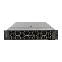
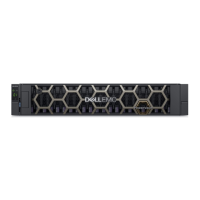
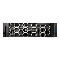
Disk drive carrier module LEDs
Disk drive status is monitored by a green LED and an amber LED mounted on the front of each drive carrier module, as shown in the
following gure.
The drive module LEDs are identied in the gure, and the LED behavior is described in the table following the gure.
• In normal operation, the green LED are on, and icker as the drive operates.
• In normal operation the amber LED will be:
– O if there is no drive present.
– O as the drive operates.
– On if there is a drive fault.
Figure 35. LEDs: Drive carrier LEDs (SFF and LFF modules) used in 2U enclosures
1
Disk Activity LED 2 Disk Fault LED
3 Disk Fault LED 4 Disk Activity LED
Table 13. Drive carrier LEDs
Activity LED (Green) Fault LED (Amber) Status/condition*
O O O (disk module/enclosure)
O O Not present
Blink o with activity Blinking: 1s on /1s o Identify
1 down: Blink with activity
2 down: O
On Drive link (PHY lane) down
On On Fault (leftover/failed/locked-out)
Blink o with activity O Available
Blink o with activity O Storage system: Initializing
Blink o with activity O Storage system: Fault-tolerant
Blink o with activity O Storage system: Degraded (not critical)
Blink o with activity Blinking: 3s on/ 1s o Storage system: Degraded (critical)
On O Storage system: Quarantined
Troubleshooting and problem solving 35

 Loading...
