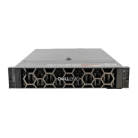
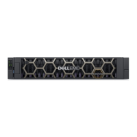
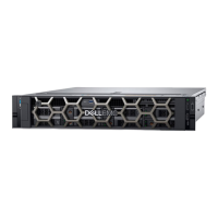
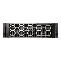
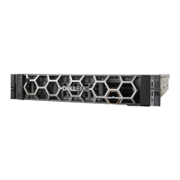
Item Enclosure component description
4 Midplane PCB (included with chassis; not available separately)
5 Power cooling module (PCM) available as AC unit (chassis uses two PCMs of same model type)
6 Expansion module for storage expansion I/O (used when chassis is congured as an EBOD)
a) 3-port 12 Gb/s SBB expansion module
7 Controller module host interfaces for storage system (used when chassis is congured as an RBOD)
a) ME4 Series 4-port FC/iSCSI supports (16 Gb/s FC and 10 GbE iSCSI) qualied SFP options*
b) ME4 Series 4-port mini-SAS (12 Gb/s) supports various qualied SFF-8644 to SFF-8644
c) ME4 Series 4-port 10Gbase-T (10 Gb/s or 1 Gb/s)
8 Small form-pluggable SFP connectors
a) SFP transceiver: 16 Gb/s FC and 10 GbE iSCSI
9 Rail kit (variable attachment options)
a) 2U rack mount kit, shelf, short, all HW
10 Cable kit [Cable package: standard HD mini-SAS (SFF-8644) to HD mini-SAS (SFF-8644)]
Cable kit [Cable package: 3.5mm; CLI
11 AC power cable compatible with AC PCM
*ME4 Series models support FC and iSCSI SFPs used in combination.
NOTE: Figure 38. SBB IOMs used in ME4 Series storage enclosures shows pictorial representations of controller modules and
expansion modules used in 2U 24-drive ME4 Series enclosures. Modules are shown oriented for insertion into IOM slot A located
on the 2U enclosure rear panel. This orientation also applies to both IOM slots in 5U84 enclosures.
52 Module removal and replacement

 Loading...
