5. Assembly and Disassembly Procedures (continued)
2
Go to contents page
DELL C8618QT
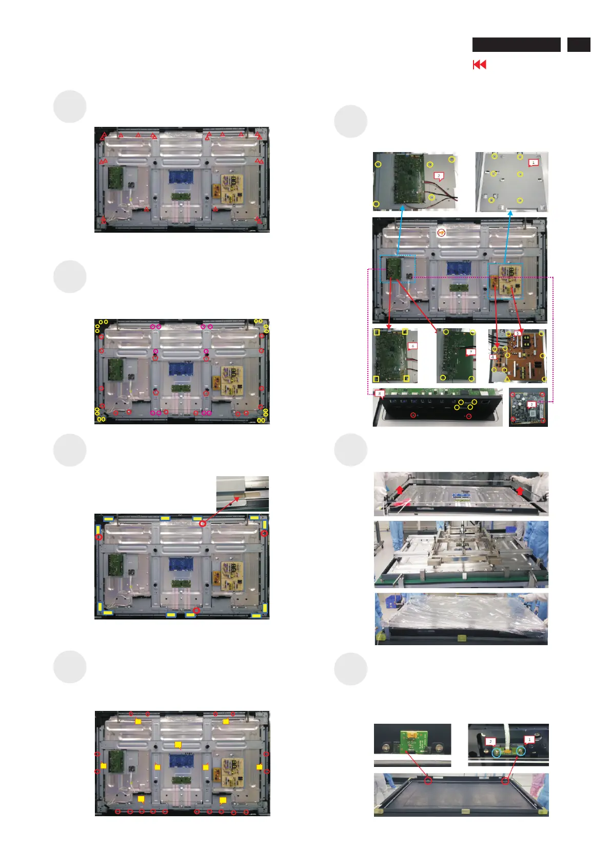
Lift up the assembled ED unit. Lift up the panel module
with a euipment and put it on a protective cushion. Lift
up the glass with a tool and put it on a protector.
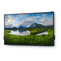
Use a screwdriver to remove 39pcs(28+11) screws for
unlocking main board, USB board, power board, AC
boar, touch board, IO stand, connectors, power board
stand and main board stand. . (Torque: 3.8kgf±0.3)
S11
Use a screwdriver to remove 2pcs screws for
unlocking the function key board with lens, to remove
2pcs screws for unlocking IR board from the IR
lens , remove 24pcs(8+16) screws for
unlocking the angle irons with front frames.
(Torque: 2±0.2kgf)
S12
Use a screwdriver to remove 12pcs screws for
unlocking the corner irons, to remove 24pcs screws
for unlocking the irons.
to remove 4pcs screws for
unlocking the vertical irons.
(Torque: 7±0.3kgf)
(Torque: 24±1kgf)
Use a screwdriver
Remove 12pcs rubbers (yellow color) and 4pcs
conductive tapes (red color) as the picture below
shown.
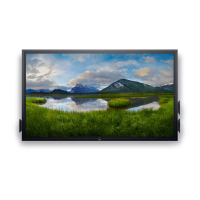
Use a screwdriver to remove 18pcs screws for
unlocking the top iron, left iron, right iron and speaker
irons with the whole unit.
Remove the top iron, left iron, right iron and speaker
irons, vertical irons, horizontal iron and corner irons.
(Torque:7kgf±0.3)
5
6
1
2
4
3
7
8
9
Use a screwdriver to remove 20pcs screws for
unlocking the irons. (Torque: 3.8±0.3kgf)
S7
S6
S8
S9
S10
ED unit
IR board
function key board
 Loading...