3 Remove the following:
a Air shroud
b All expansion cards and risers
c Internal PERC riser
d vFlash/IDSDM module
e Internal USB key (if installed)
f USB 3.0 module (if installed)
g Processors and heat sink modules
h Processors blanks (if applicable)
CAUTION: To prevent damage to the processor socket when replacing a faulty system board, ensure that
you cover the processor socket with the processor dust cover.
i Memory modules and memory module blanks
j LOM riser card
k Drive cage (rear) (if applicable)
Steps
1 Disconnect all cables from the system board.
CAUTION: Take care not to damage the system identication button while removing the system board from the chassis.
CAUTION: Do not lift the system board by holding a memory module, processor, or other components.
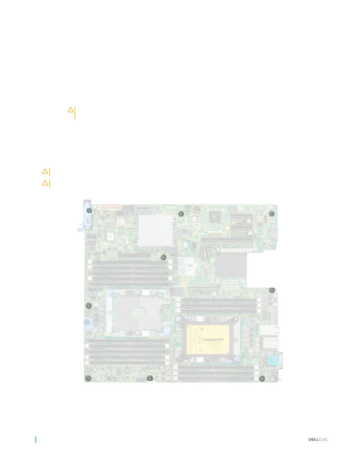
2 Using Phillips #2 screwdriver, remove nine screws securing the system board to the chassis.
Figure 118. System board screws
3 Hold the system board holder, slightly lift the system board, and then slide it toward the front of the chassis.
164
Installing and removing system components

 Loading...


