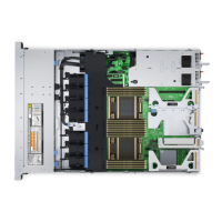
Figure 51. 24 x 2.5-inch NVMe switch with 2 front PERC
Table 41. 24 x 2.5-inch NVMe switch with 2 front PERC
From To
SIG_PWR_1 (system board power connector) BP_PWR_1 (backplane power connector)
CTRL_SRC_PA1 (fPERC controller connector) DST_PA2 (backplane switch signal connector)
CTRL_SRC_PB1 (fPERC controller connector) DST_PB2 (backplane switch signal connector)
SL3_CPU1_PB2 (signal connector on system board) CTRL_DST_PA1 (fPERC input connector)
SIG_PWR_2 (system board power connector) BP_PWR_2 (backplane power connector)
CTRL_SRC_PA1 (fPERC controller connector) DST_PA2 (backplane switch signal connector)
CTRL_SRC_PB1 (fPERC controller connector) DST_PB2 (backplane switch signal connector)
SL1_CPU2_PB1 (signal connector on system board) CTRL_DST_PA1 (fPERC input connector)
M.2 SSD module
Removing the M.2 SSD module
Prerequisites
1. Follow the safety guidelines listed in Safety instructions.
2. Follow the procedure listed in Before working inside your system.
3. Remove the air shroud.
4. Remove the BOSS card.
NOTE:
Removing the BOSS card is similar to the procedure for removing an expansion card from the expansion card
riser.
Steps
1. Loosen the screws and lift the retention straps that secure the M.2 SSD module on the BOSS card.
2. Pull the M.2 SSD module away from the BOSS card.
54
Installing and removing system components
 Loading...


