About this task
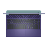
The following image indicates the connectors on your system board.
1. Display cable 2. Power-adapter port cable
3. Speaker cable 4. Keyboard cable
5. Keyboard backlit cable 6. Touchpad cable
7. Power-button cable
The following image indicates the location of the system board and provides a visual representation of the removal procedure.
Removing and installing components
41

 Loading...