Steps
1. Disconnect the WLAN, WWAN, and GPS antennas from the Wi-Fi I/O board.
Table 2. Cable connectors on Latitude 5430 Rugged
Cable number Antenna
5 WWAN antenna on Wi-Fi I/O board
1 WWAN antenna on Wi-Fi I/O board
12 WWAN antenna on Wi-Fi I/O board
2 WLAN antenna on Wi-Fi I/O board
13 WLAN antenna on Wi-Fi I/O board
10 WLAN antenna on Wi-Fi I/O board
11 GPS antenna on Wi-Fi I/O board
14 GPS antenna on Wi-Fi I/O board
4 GPS antenna on Wi-Fi I/O board
2. Peel the adhesive tape and disconnect the flexible printed cable from the Wi-Fi I/O board.
3. Remove the two (M2.5x5) screws that secure the Wi-Fi I/O board to the system board.
4. Lift the Wi-Fi I/O board from the system board.
Installing the Wi-Fi I/O board
Prerequisites
If you are replacing a component, remove the existing component before performing the installation procedure.
About this task
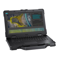
The following image indicates the location of the Wi-Fi I/O board and provides a visual representation of the installation
procedure.
Removing and installing components
43
 Loading...
