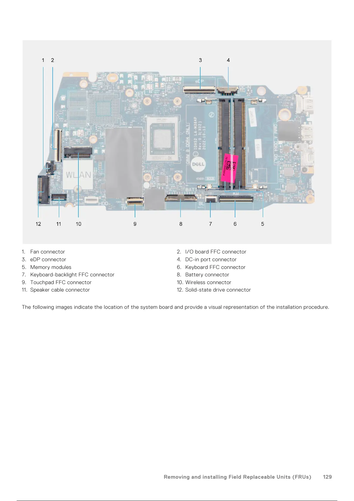
1. Fan connector 2. I/O board FFC connector
3. eDP connector 4. DC-in port connector
5. Memory modules 6. Keyboard FFC connector
7. Keyboard-backlight FFC connector 8. Battery connector
9. Touchpad FFC connector 10. Wireless connector
11. Speaker cable connector 12. Solid-state drive connector
The following images indicate the location of the system board and provide a visual representation of the installation procedure.
Removing and installing Field Replaceable Units (FRUs)
129
130 / 156 129 / 154 130 / 156