VERSION 1.0 5
DELL™ OPTIPLEX™ 740 TECHNICAL GUIDE
55
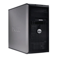
Mini towEr coMputEr (Mt) viEw
SYSTEM BOARD COMPONENTS
6
password jumper (PSWD)
7
SATA drive connectors (SATA0, SATA1, SATA2, SATA3)
8
front-panel connector (FRONTPANEL)
9
power connector (POWER)
10
internal USB (INT_USB)
11
RTC reset jumper (RTCRST)
12
intrusion switch connector (INTRUDER)
13
battery socket (BATTERY)
14
PCI Express x16 connector (SLOT1)
15
PCI Express x1 connector (SLOT4)
16
PCI connector (SLOT2)
17
PCI connector (SLOT3)
18
serial connector (SERIAL2)
19
aux power LED (aux_LED)
20
oppy connector (DSKT)
21
optional DVI-card connector (DVI_HDR)
22
VGA connector
23
parallel port
24
serial port
25
USB 2.0 connector (3)
26
RJ 45 network port
27
USB 2.0 connector (2)
28
stereo-in/microphone
29
stereo out
FRONT VIEW
1
5.25-inch drive bay
2
5.25-inch drive bay
3
3.5-inch drive bay
4
USB 2.0 connectors (2)
5
LAN indicator light
6
diagnostic lights
7
power button
8
power light
9
hard drive activity light
10
headphone connector
11
microphone connector
BACK VIEW
1
cover-release latch
2
padlock ring
3
voltage selection switch
4
power connector
5
VGA port
6
parallel port
7
serial port
8
card slots (4)
SYSTEM BOARD COMPONENTS
1
speaker connector (INT_SPKR)
2
fan (FAN_CPU)
3
processor connector (CPU)
4
processor power connector (12VPOWER)
5
memory module connectors (DIMM_1, DIMM_2, DIMM_3, DIMM_4)
20
22
24
23
25
26
28
27
29
21
18
12
13
14
16
19
17
15
11
10
1
2
3
4
5
6
7
7
8
9
1
2
3
8
4
9
11
10
5
6
7
8
1
2
3
4
5
7
6

 Loading...