Dell
20
PowerEdge R415 Technical Guide
3.12.1 LED Panel Configuration
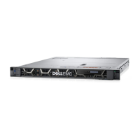
Figure 14 and Figure 15 show the LED panel.
Figure 14. LED panel Configuration
Figure 15. LED Panel (Detailed View)
For a complete description of LED indicators, their causes, and possible courses of action to take to resolve
an error, see the Diagnostic Lights (Optional) section in the About Your System chapter in the PowerEdge
R415 Hardware Owner’s Manual on Support.Dell.com.
3.12.2 LCD Panel Configuration
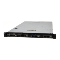
Figure 16 and Figure 17 show the LCD panel.
Figure 16. LCD Panel Configuration
Figure 17. LCD Panel (Detailed View)
The LCD panel is located on the front of the system chassis to provide user access to buttons, display, and
I/O interfaces. Features of the LCD panel include the following:
• ACPI-compliant power button with an integrated green power LED (controlled by iDRAC6)
• 128x20 pixel LCD screen with controls
• Two navigation buttons
• Select button
• System ID button
• Non-maskable Interrupt (NMI) button (recessed)
• Ambient temperature sensor
 Loading...