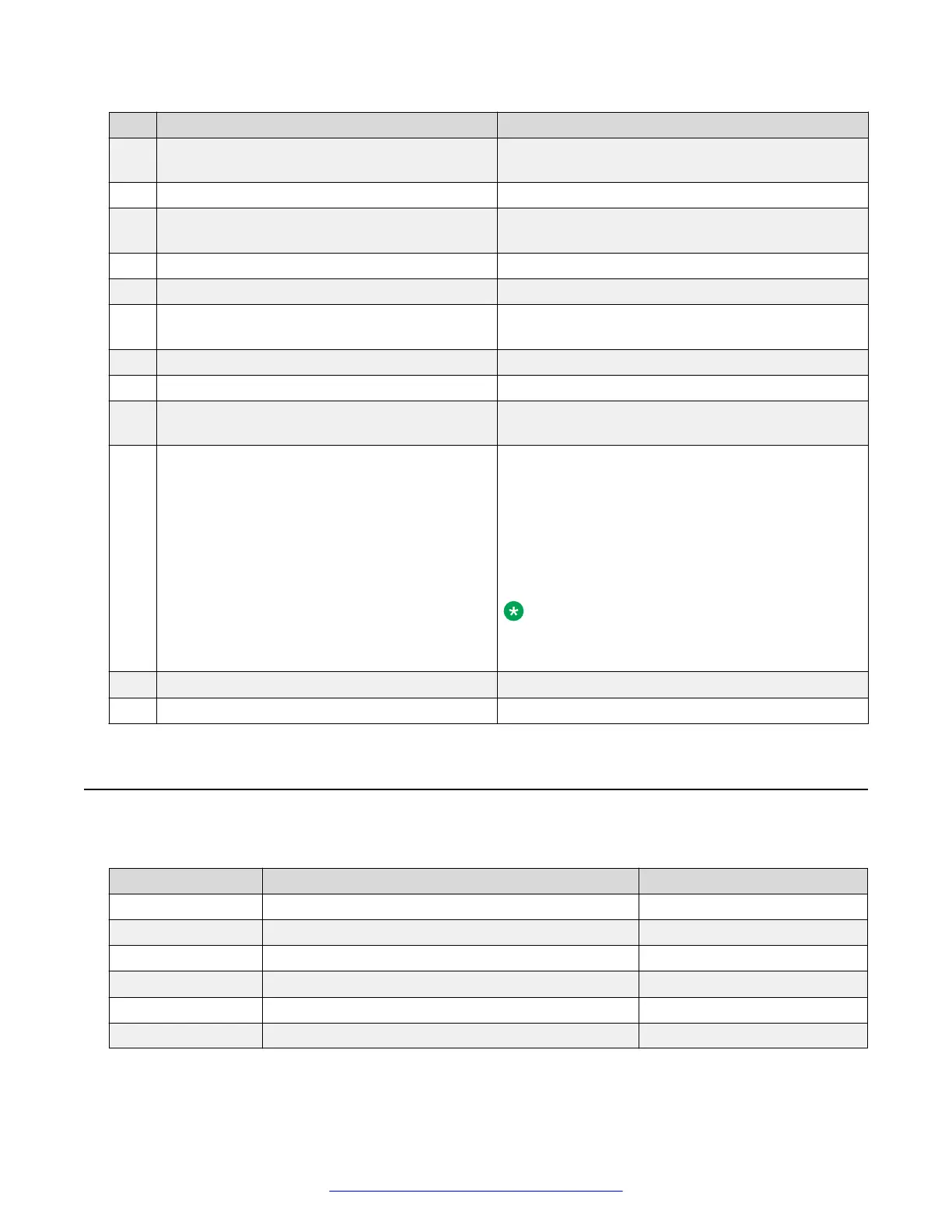
No. Description Avaya recommendation
2 VFlash media slot (optional) Connects an external SD memory card for the
optional iDRAC6 Enterprise/Express card.
3 Serial connector
4 PCIe slot 1 Consult application/solution documentation for
specific behavior of the optional card in this slot.
5 Video connector
6 USB connectors (2)
7 PCIe slot 2 Consult application/solution documentation for
specific behavior of the optional card in this slot.
8 Ethernet connectors (4)
9 System status indicator connector
10 System status indicator Provides a power on indicator for the back of the
system.
11 System identification button Turns the system ID modes on and off.
The identification buttons on the front and back
panels can be used to locate a particular system
within a rack. When one of these buttons is pushed,
the LCD panel on the front and the system status
indicator on the chassis back panel flash blue until
one of the buttons is pushed again.
Note:
Some applications/solutions use this light for
additional functionality.
12 Power supply 1 (PS1)
13 Poser supply 2 (PS2)
Troubleshooting external server components
Use the checklist below to troubleshoot any of the following external server components:
Part number
Description Hot-swappable?
700501316 R610 SRVR 146GB 10K SAS 2.5” HDD Y
700501317 R610 SRVR 146GB 15K SAS 2.5” HDD Y
700501315 R610 SRVR 300GB 10K SAS 2.5” HDD Y
700501421 R610 SRVR 600GB 10K SAS 2.5" HDD Y
700501183 R610 SRVR AC PWR SUP 502W ES Y, if redundant
700501311 R610 SRVR AC PWR SUP 717W Y, if redundant
Maintaining and Troubleshooting the Dell
™
PowerEdge
™
R610 Server
10 Maintaining and Troubleshooting the Dell
™
PowerEdge
™
R610 Server November 2010
Comments on this document? infodev@avaya.com

 Loading...


