Table 38. Expansion card installation priority (continued)
Card Priority Card Type Systems Supporting up to 2 PCIe
Expansion Cards
Systems Supporting up to 3 PCIe
Expansion Cards
Slot Priority Max Allowed Slot Priority Max Allowed
4 40 G NICs 2, 1 2 3, 2 2
5 FC16 HBA 2, 1 2 3, 2, 1 3
6 10 Gb NICs 2, 1 2 3, 2, 1 3
7 FC8 HBA 2, 1 2 3, 2, 1 3
8 1 Gb NICs 2, 1 2 3, 2, 1 3
9 Non-RAID 12 Gb SAS 1 1 3, 1 2
10 Integrated RAID Integrated Slot 1 Integrated Slot 1
11 NDC Integrated Slot 1 Integrated Slot 1
12 NVMe PCIe SSD 1,2 2 3, 2, 1 2
NOTE: To support x16 PCIe link width, the 100 G HCA/OPA HFI in slot 1 needs processor 2 and x16 center_riser2.
Removing expansion card risers
1. Follow the safety guidelines listed in the Safety instructions section.
2. Follow the procedure listed in the Before working inside your system section.
CAUTION:
Many repairs may only be done by a certified service technician. You should only perform
troubleshooting and simple repairs as authorized in your product documentation, or as directed by the online or
telephone service and support team. Damage due to servicing that is not authorized by Dell is not covered by
your warranty. Read and follow the safety instructions that are shipped with your product.
NOTE: The expansion card riser 1 and the x16 link on the riser 2 slot can be used only when both the processors are
installed.
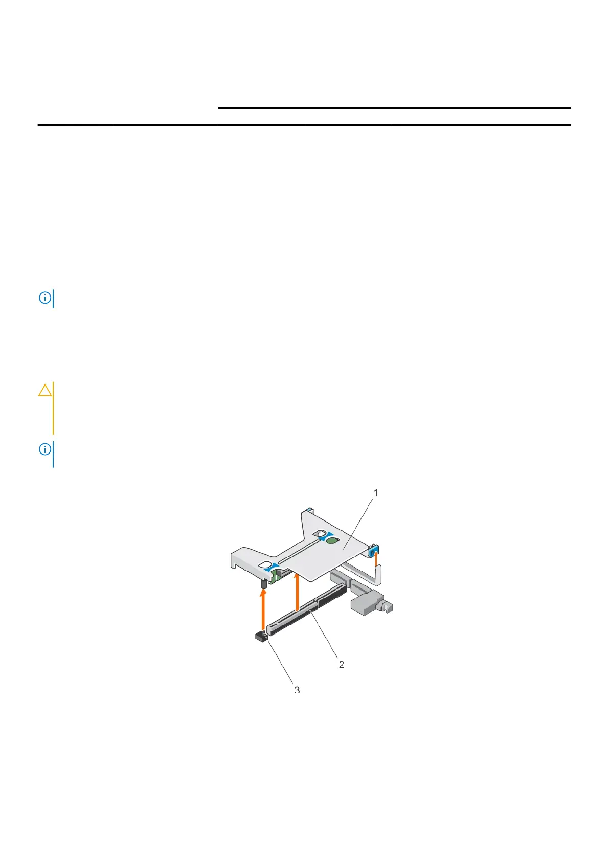
1. Holding the touch points, lift the expansion card riser from the riser connector on the systemboard.
Figure 47. Removing the expansion card riser 1
a. expansion card riser 1
b. connector
c. riser guide pin
98
Installing and removing system components

 Loading...