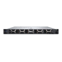
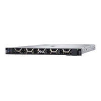
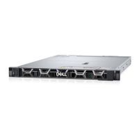
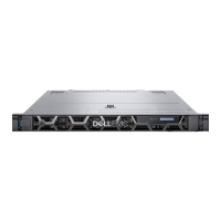
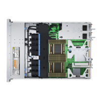
Figure 83. Configuration 6-2: 16 x E3.S G5x4 Dual RAID
NOTE:
Follow the sequential order as shown in the table to remove the cables, to install the cables follow the reverse
sequential order.
Table 85. 16 x E3.S G5x4 Dual RAID
Order From To
1 SIG_PWR_1 (system board power connector) BP_PWR_1 (backplane power connector)
2 SIG_PWR_2 (system board power connector) BP_PWR_1 (backplane power connector)
3 SL1 (signal connector on system board) CTRL_DST_PA1 (front PERC)
4 SL7 (signal connector on system board) CTRL_DST_PA1 (front PERC)
5 CTRL_SRC_PA1 (front PERC) BP_DST_PA1 and BP_DST_PB1 (backplane signal
connector)
6 CTRL_SRC_PB1 (front PERC) BP_DST_PA2 and BP_DST_PB2 (backplane signal
connector)
7 SL3 (signal connector on system board) CTRL_DST_PB1 (front PERC)
8 SL8 (signal connector on system board) CTRL_DST_PB1 (front PERC)
PERC module
This is a service technician replaceable part only.
Removing the front mounting front PERC module
Prerequisites
1. Follow the safety guidelines listed in the Safety instructions.
2. Follow the procedure listed in the Before working inside your system.
3. Remove the drive backplane cover.
4. If installed, remove the air shroud.
Installing and removing system components
111

 Loading...
