2. If removed, install the air shroud or install the GPU air shroud.
3. If removed, install the drive backplane cover.
4. Follow the procedure listed in the After working inside your system.
Cable routings
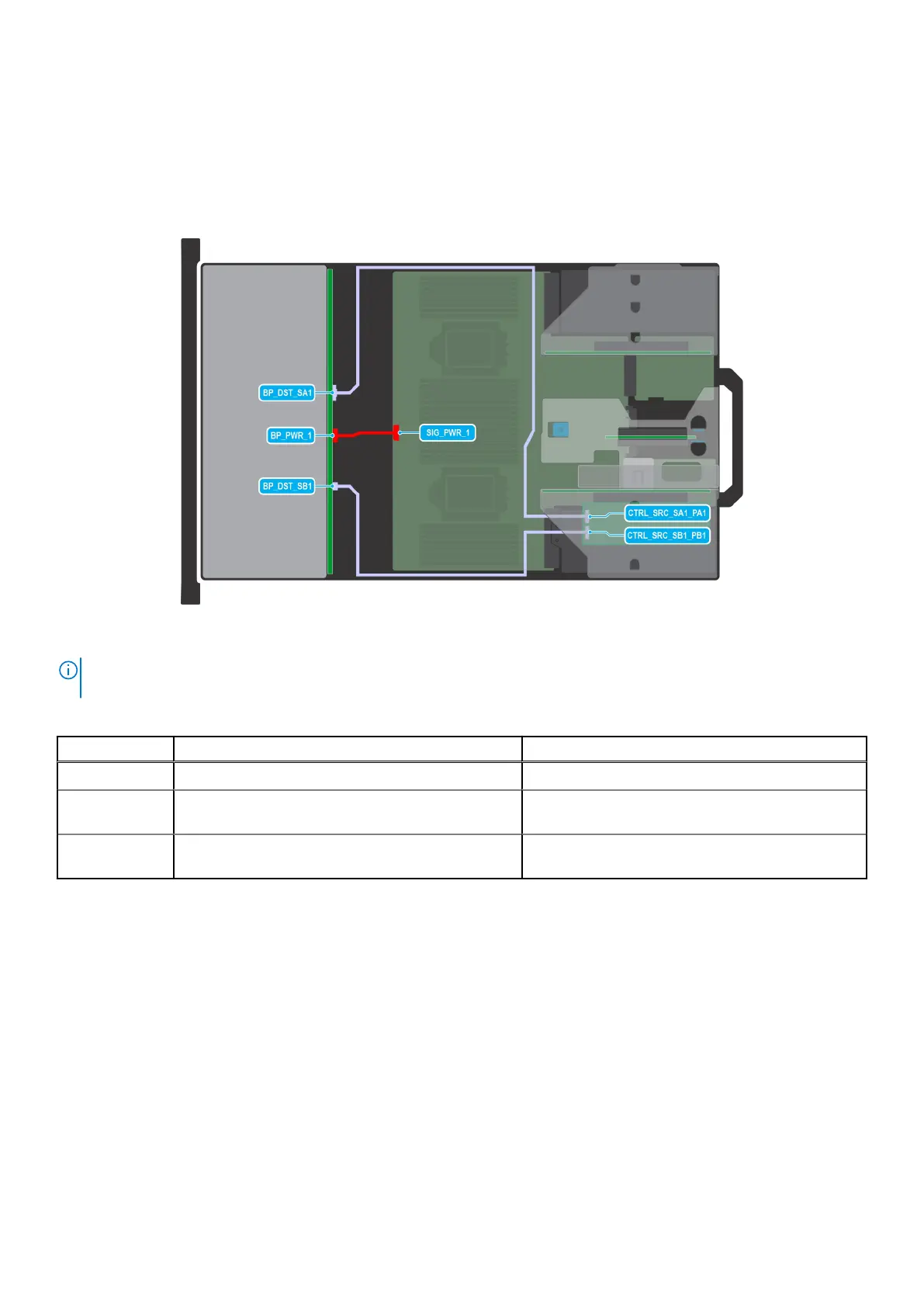
Figure 76. Configuration 0: 12 x 3.5-inch SAS/SATA with APERC in Riser 1
NOTE:
Follow the sequential order as shown in the table to remove the cables, to install the cables follow the reverse
sequential order.
Table 79. 12 x 3.5-inch SAS/SATA with APERC in Riser 1
Order From To
1 SIG_PWR_1 (system board power connector) BP_PWR_1 (backplane power connector)
2 CTRL_SRC_SA1_PA1 (adapter PERC controller
connector)
BP_DST_SA1 (backplane signal connector)
3 CTRL_SRC_SB1_PB1 (adapter PERC controller
connector)
BP_DST_SB1 (backplane signal connector)
Installing and removing system components 123

 Loading...