132 Installing System Components
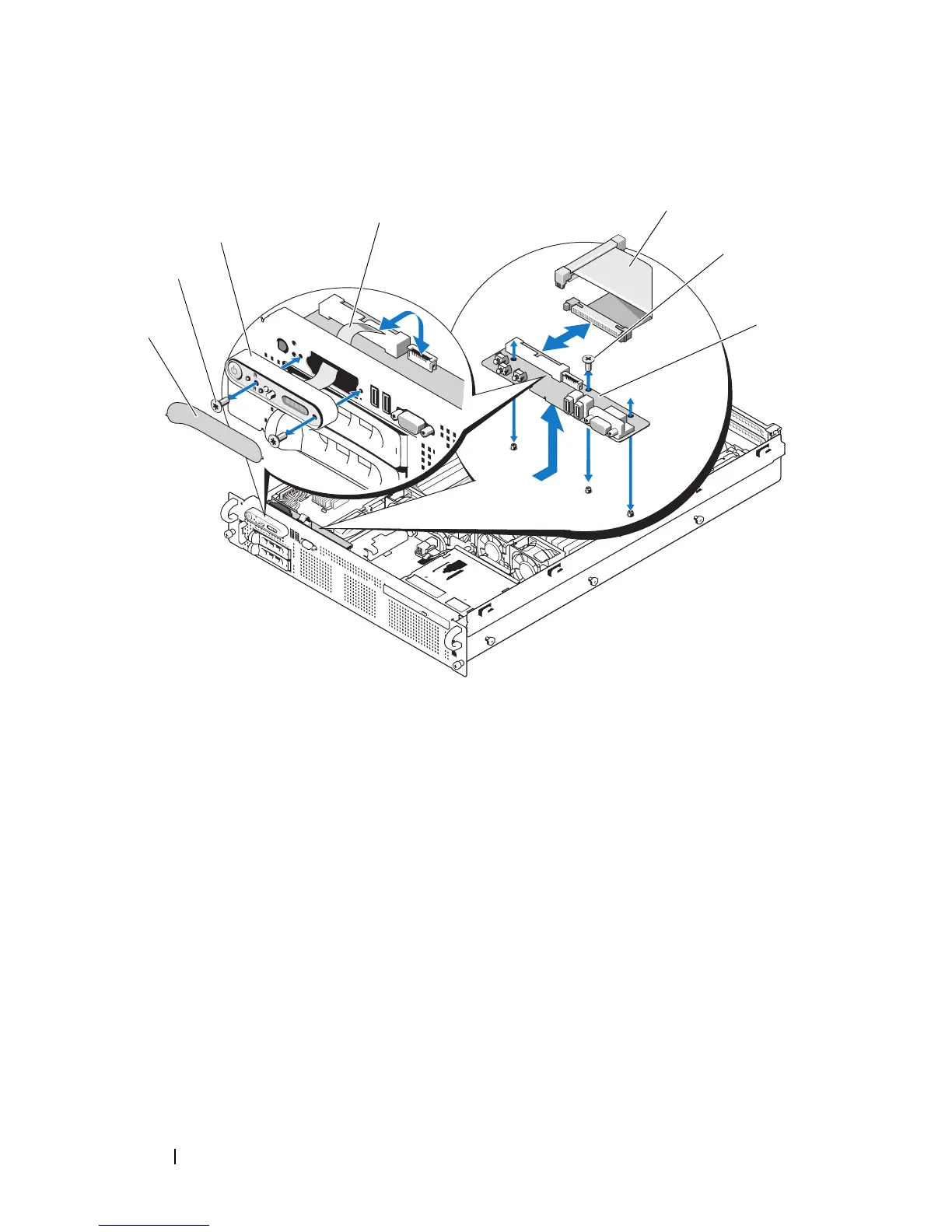
Figure 3-31. Control Panel Removal
5
Disconnect the display module cable from the control panel board. See
Figure 3-31.
6
Remove the three screws that secure the control panel board to the system
chassis and remove the board. See Figure 3-31.
1 display module label 2 display module securing screws (2)
3 display module 4 display module cable
5 control panel cable 6 control-panel circuit board securing
screws (3)
7 control panel circuit board
7
2
3
4
6
1
5
 Loading...