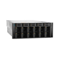
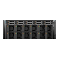
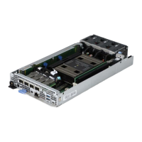
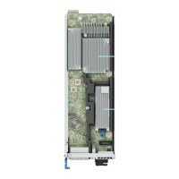
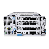
Figure 115. Installing the GPU assembly and cable
4. Reconnect the cables from the LAAC GPU Dip Tray connector on to the PDB.
5. Holding botht the handles, align and lower tray along the guiding features with their corresponding marks on the chassis until
the tray locks in its place. Push the handles in its locking position. Lock the two blue thumb screws on the LAAC GPU Dip
tray and two blue thumb screws on the LAAC Radiator handles.
Figure 116. Installing the LAAC GPU Dip tray
Next steps
1. Replace the System board tray.
2. Follow the procedure listed in After working inside your system.
Installing and removing system components
139

 Loading...
