Do you have a question about the Dell SFP and is the answer not in the manual?
Estimates the duration for replacing an SFP or XFP transceiver.
Lists the necessary components and tools for transceiver replacement.
This document outlines the procedure for replacing Small Form-Factor Pluggable (SFP), SFP+, and 10 Gigabit Small Form-Factor Pluggable (XFP) optical transceivers. These transceivers are critical components for establishing optical network connections, converting electrical signals into optical signals and vice-versa, enabling data transmission over fiber optic cables. The guide is designed to assist users in safely and efficiently performing transceiver replacements, ensuring proper functionality and minimizing downtime.
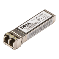
The primary function of these optical transceivers is to provide the interface between a network device (such as a switch or blade) and a fiber optic cable. They are essential for high-speed data communication in various networking environments, including data centers, enterprise networks, and storage area networks (SANs). SFP, SFP+, and XFP modules support different data rates and distances, allowing for flexibility in network design and deployment. SFP modules generally support data rates up to 1 Gigabit per second (Gbps), SFP+ modules support up to 10 Gbps, and XFP modules also support 10 Gbps but typically have a larger form factor and different electrical interface. The document specifically notes that XFP transceivers are used only with the FC10-6 port card, indicating a specialized application within certain Dell systems.
The replacement procedure itself is designed to be straightforward and quick, with an estimated time requirement of less than five minutes for an SFP or XFP replacement. This efficiency is crucial in maintaining network uptime and reducing the impact of hardware maintenance. The process involves a few key steps: preparing the necessary tools and components, safely removing the existing transceiver, and correctly installing the new one.
For usage features, the document highlights the physical arrangement of transceivers within switches and blades. They are typically arranged in two rows, back to back. On most switches and the DCX-4S Backbone, the bottom row of transceivers is oriented upside down relative to the top row. This detail is important for users to correctly identify and manipulate the transceivers during replacement. The transceivers are "keyed," meaning they have a specific physical shape that ensures they can only be inserted into the port in the correct orientation. This design feature prevents incorrect installation and potential damage to both the transceiver and the port. Similarly, fiber optic cables are also keyed, ensuring they can only be inserted into the transceiver in one way, further simplifying the connection process and reducing the risk of errors.
Maintenance features are primarily focused on the tools and techniques required for safe and effective replacement. The essential items required for the procedure include the replacement SFP, SFP+, or XFP module itself, and an optical transceiver extraction tool. Most Brocade switches and backbones are supplied with such an extraction tool and a holster for it. The extraction tool is specifically designed to facilitate the removal of transceivers from switches and blades where space is limited, which is a common challenge in dense networking equipment. This tool helps in disengaging the cable latching mechanism and pulling the transceiver out without damaging adjacent components or the transceiver itself.
The removal process involves two main steps. First, any cables inserted into the transceiver must be removed. The extraction tool is used here to open the cable latching mechanism, allowing for easy disconnection. Second, the "bail" (a wire handle) on the transceiver needs to be pulled away from its pivot point and out. This action slides the transceiver out of its slot in the switch or blade. This mechanical design of the bail provides a simple and effective way to release and extract the module.
The replacement process for a new transceiver is equally detailed. The user must first position the optical transceiver so that its key is correctly oriented to the port. It is then inserted into the port until it is firmly seated and the latching mechanism clicks. The document reiterates the importance of the "keying" feature, advising users that if a transceiver does not slide in easily, they should ensure it is correctly oriented rather than forcing it. After the transceiver is installed, the fiber optic cable is connected. The cable's key (a ridge on one side of the connector) must be aligned with the slot in the transceiver, and the cable is then inserted until its latching mechanism clicks. Again, the document emphasizes that cables are keyed to prevent incorrect insertion, and if a cable does not slide in easily, its orientation should be checked.
Safety and regulatory information are also integral to the document, emphasizing responsible handling of the equipment. The guide includes standard warnings and notes. A "NOTE" indicates important information to help users make better use of their computer or system. A "CAUTION" warns of potential damage to hardware or loss of data if instructions are not followed, and directs users to consult the safety and regulatory information that shipped with their system, as well as the Regulatory Compliance Homepage on www.dell.com. A "DANGER" indicates a potential for property damage, personal injury, or death, underscoring the critical importance of adhering to safety guidelines. These warnings ensure that users are aware of the risks involved and take necessary precautions during the replacement procedure.
The document also includes legal disclaimers, stating that the information is subject to change without notice and that reproduction of the materials without written permission from Dell Inc. is forbidden. It lists various trademarks and trade names, clarifying proprietary interests. This standard legal information ensures compliance and protects intellectual property.
In summary, this manual provides a clear, concise, and practical guide for replacing SFP, SFP+, and XFP optical transceivers. It covers the functional aspects of these components, details the step-by-step usage and maintenance procedures, and incorporates essential safety warnings. The emphasis on ease of use, quick replacement times, and built-in error prevention mechanisms (like keying) makes the process accessible even for users with moderate technical expertise, ensuring reliable network operation and simplified hardware management.
| Form Factor | SFP |
|---|---|
| Data Rate | 1 Gbps |
| Connector Type | LC |
| Cable Type | Fiber Optic |
| Operating Temperature | 0°C to 70°C |
| Wavelength | 850nm |
| Distance | 550 meters |
| Fiber Type | Single-mode or multimode |
| Compatibility | Dell Networking |