Identifier GUID-2DF70EB1-9D26-4051-8B7C-FB14A89925D8
Status Released
Replacing the display assembly
WARNING: Before working inside your computer, read the safety
information that shipped with your computer and follow the steps in Before
working inside your computer. After working inside your computer, follow
the instructions in After working inside your computer. For more safety best
practices, see the Regulatory Compliance home page at www.dell.com/
regulatory_compliance.
Identifier GUID-DA82B76C-0EE3-4263-9033-54BF36A6B5B6
Status Released
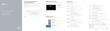
Procedure
1 Place the palm-rest assembly at the edge of the table with the speakers facing
away from the edge.
2 Align the screw holes on the palm-rest assembly with the screw holes on the
display hinges.
3 Replace the six screws (M2.5x5) that secure the display hinges to the palm-rest
assembly.
4 Adhere the tape and route the touch-screen cable (optional) through the routing
guides on the fan.
5 Connect the touch-screen cable and display cable to the system board.
NOTE: The touch-screen cable is available only on laptop congurations
with touch displays.
6 Replace the screw (M2x2) that secures the display-cable bracket to the system
board.
84
 Loading...