Do you have a question about the DeLonghi CLIMAVENETA HED HCAT 0011 SE and is the answer not in the manual?
| Brand | DeLonghi |
|---|---|
| Model | CLIMAVENETA HED HCAT 0011 SE |
| Category | Air Conditioner |
| Language | English |
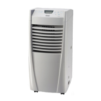
Provides data identifying the product.
Details technical and performance data of the unit.
Describes the unit's construction, panelling, and insulation.
Details the coil's material and construction for heat exchange.
Describes the type and characteristics of the fan used.
Explains the power and control switchboard compliance.
Details the heating element module and its power rating.
Guidance on selecting an appropriate installation site for the unit.
Instructions on handling and positioning the unit correctly.
Importance of correct pipe sizing for operation.
Procedures for creating flange connections and pipe cleanliness.
Steps for connecting the liquid pipe and insulation.
Details on connecting the unit to the power supply and circuit breaker.
Procedure for cleaning and checking air filters.
Steps to inspect and maintain the heat exchange coil.
How to check the unit's overall preservation and rust formation.
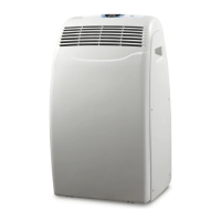
Provides data identifying the product.
Details technical and performance data of the unit.
Describes the unit's construction, panelling, and insulation.
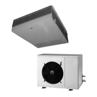
Details the type and features of the compressor.
Describes the condenser's construction and connections.
Describes the fan type, balancing, and motor.
Explains the refrigerant circuit components and testing.
Details the electrical panel construction and control.
Lists optional accessories available for the unit.
Guidance on selecting an appropriate installation site for the unit.
Instructions on handling and positioning the unit correctly.
Importance of correct pipe sizing for operation.
Instructions for insulating, siphoning, and installing intake/discharge pipes.
Guidance on selecting pipe diameters and insulation for liquid lines.
Table for sizing pipes based on equivalent distance.
Data for calculating equivalent pipe lengths for curves and siphons.
Procedure for connecting intake piping with flared couplings.
Procedure for connecting liquid piping with flared couplings.
Shows main measurement values like temperature and compressor status.
Displays alarm status and logs the last 100 alarms.
How to enter menus to edit unit operating parameters.
Displays current machine status, temperature, and humidity.
Access to submenus like MAINTENANCE MAN and MANUFACTURER.
Displays temperature set point and humidity.
Configures damper offset and enable/disable damper function.
Used to change the maintenance man password.
Configures BMS network, printer, and temperature units.
Sets refrigerant type and freecooling operation.
Enables or disables the humidifying or dehumidifying function.
Instructions on assigning addresses using dip switches for network operation.
Defines participation class for pLAN of boards 1-3, 4-6, and 7-8.
Sets number of stand-by units and automatic rotation interval.
Enables support and sets forcing delays for ambient temperature.
Configures differential and offset for low ambient temperature.
Configures differential and offset for high ambient temperature.