^F
77
!
fnW\
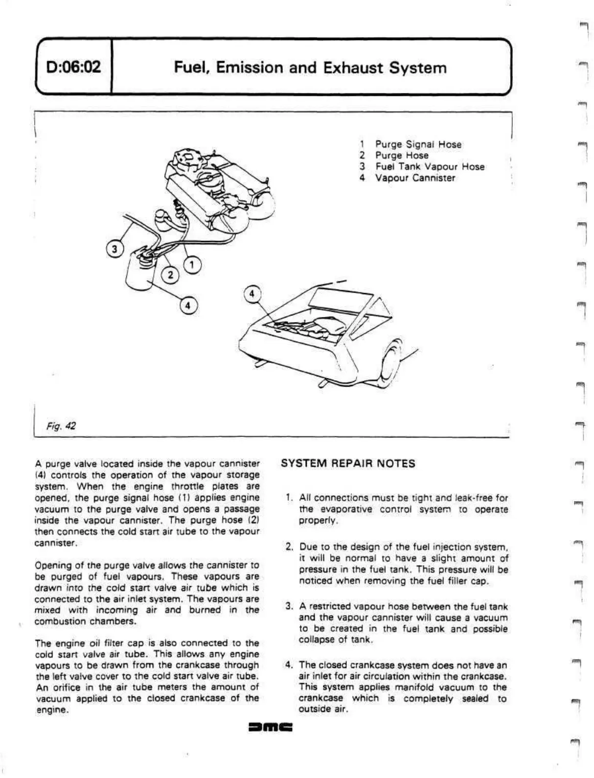
1 Purge Signal Hose
2 Purge Hose
3 Fuel Tank Vapour Hose
4 Vapour Cannister
^•••''r
Fig.
42
A purge valve located inside the vapour cannister
(4) controls the operation of the vapour storage
system.
When the engine throttle plates are
opened,
the purge signal hose (1) applies engine
vacuum to the purge valve and opens a passage
inside the vapour cannister. The purge hose (2)
then connects the cold start air tube to the vapour
cannister.
Opening of the purge valve allows the cannister to
be purged of fuel vapours. These vapours are
drawn into the cold start valve air tube which is
connected to the air inlet system. The vapours are
mixed with incoming air and burned in the
combustion chambers.
The engine oil filter cap is also connected to the
cold start valve air tube. This allows any engine
vapours to be drawn from the crankcase through
the left valve cover to the cold start valve air tube.
An orifice in the air tube meters the amount of
vacuum applied to the closed crankcase of the
engine.
SYSTEM REPAIR NOTES
1.
All connections must be tight and leak-free for
the evaporative control system to operate
properly.
2.
Due to the design of the fuel injection system,
it will be normal to have a slight amount of
pressure in the fuel tank. This pressure will be
noticed when removing the fuel filler cap.
3. A restricted vapour hose between the fuel tank
and the vapour cannister will cause a vacuum
to be created in the fuel tank and possible
collapse of tank.
4.
The closed crankcase system does not have an
air inlet for air circulation within the crankcase.
This system applies manifold vacuum to the
crankcase which is completely sealed to
outside air.
 Loading...
