G:05:02 Automatic Transmission
SELECTOR LINKAGE ADJUSTMENT
•
1.
Place car on chassis contact hoist and place
the gear selector lever in the PARK position
with park brake off. Ensure that the lever
locking mechanism is fully seated and the lever
is locked in position.
2.
Raise the vehicle on a hoist and disconnect the
shift tube from the bellcrank lever. Fig. 10
3. Place the transmission in PARK by rotating the
bellcrank lever by hand. Ensure that the
transmission is in the PARK position by
holding one rear wheel and attempt to rotate
the other rear wheel. The parking pawl should
drop into position and lock the wheel.
4.
Unlock the shift tube adjustment nut and
lengthen or shorten the tube until it will slip
over the bellcrank mounting
stud.
5. Tighten the shift tube adjustment nut lock and
connect the tube to the bellcrank.
6. Lower the vehicle on hoist.
.
TO SELECTOR
/
LEVER
/BELLCRANK
/
LEVER
TO
TRANSMISSION-^
-**V.
Fig. 10 SHIFT TUBE ADJUSTMENT
GOVERNOR CONTROL CABLE
ADJUSTMENT
1.
Raise the vehicle on a hoist.
2.
With the engine turned off, use a suitable
weight to depress the accelerator pedal to the
floor (full throttle position). Check to ensure
full throttle at engine is achieved.
3. Perform throttle cable adjustments if the
throttle is not opening to the maximum before
proceeding.
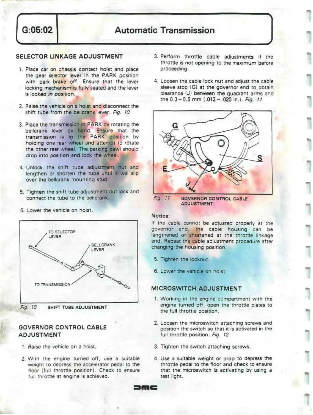
4.
Loosen the cable lock nut and adjust the cable
sleeve stop (G) at the governor end to obtain
clearance (J) between the quadrant arms and
the 0.3-0.5 mm (.012- .020 in.). Fig.
11
Fig.
11 GOVERNOR CONTROL CABLE
ADJUSTMENT
Notice:
If the cable cannot be adjusted properly at the
governor end, the cable housing can be
lengthened or shortened at the throttle linkage
end.
Repeat the cable adjustment procedure after
changing the housing position.
5. Tighten the locknut.
6. Lower the vehicle on hoist.
MICROSWITCH
ADJUSTMENT
1.
Working in the engine compartment with the
engine turned off, open the throttle plates to
the full throttle position.
2.
Loosen the microswitch attaching screws and
position the switch so that it is activated in the
full throttle position. Fig. 12
3. Tighten the switch attaching screws.
4.
Use a suitable weight or prop to depress the
throttle pedal to the floor and check to ensure
that the microswitch is activating by using a
test light.
 Loading...
