pgyHhEfiniKumu
Steering
H:06i01
REMOVAL
RACK AND PINION ASSEMBLY
-
REPLACE
INSTALLATION
jfflJH
^
1.
Raise
car
on hoist.
2.
Remove both front tyre and wheel assemblies.
3. Remove both
tie'rod
ends to
-steering
knuckle
nuts and separate tie rod
epds
from steering
knuckles^with
the appropriate
tool.
4.
Remove the pinch
tjolt
securing
the-steering
column universal joint to the steering rack
"
pinion shaft.
5. Loosen pinch
bolt
securing the universal joint
to the intermediate shaft
arid
slide the universal
joint up the intermediate shaft sufficient to
disengage universal joint
from
pinion shaft.
6. Remove both pairs of steering rack clamp nuts
and remove the
clamps.
,7.Reniove the
la'teral
restraint bracket from
underneath the
RH
rubber steering mount
rack.
8. Remove rubber mounts by rotating mounts
and prying them off rack and pinion assembly.
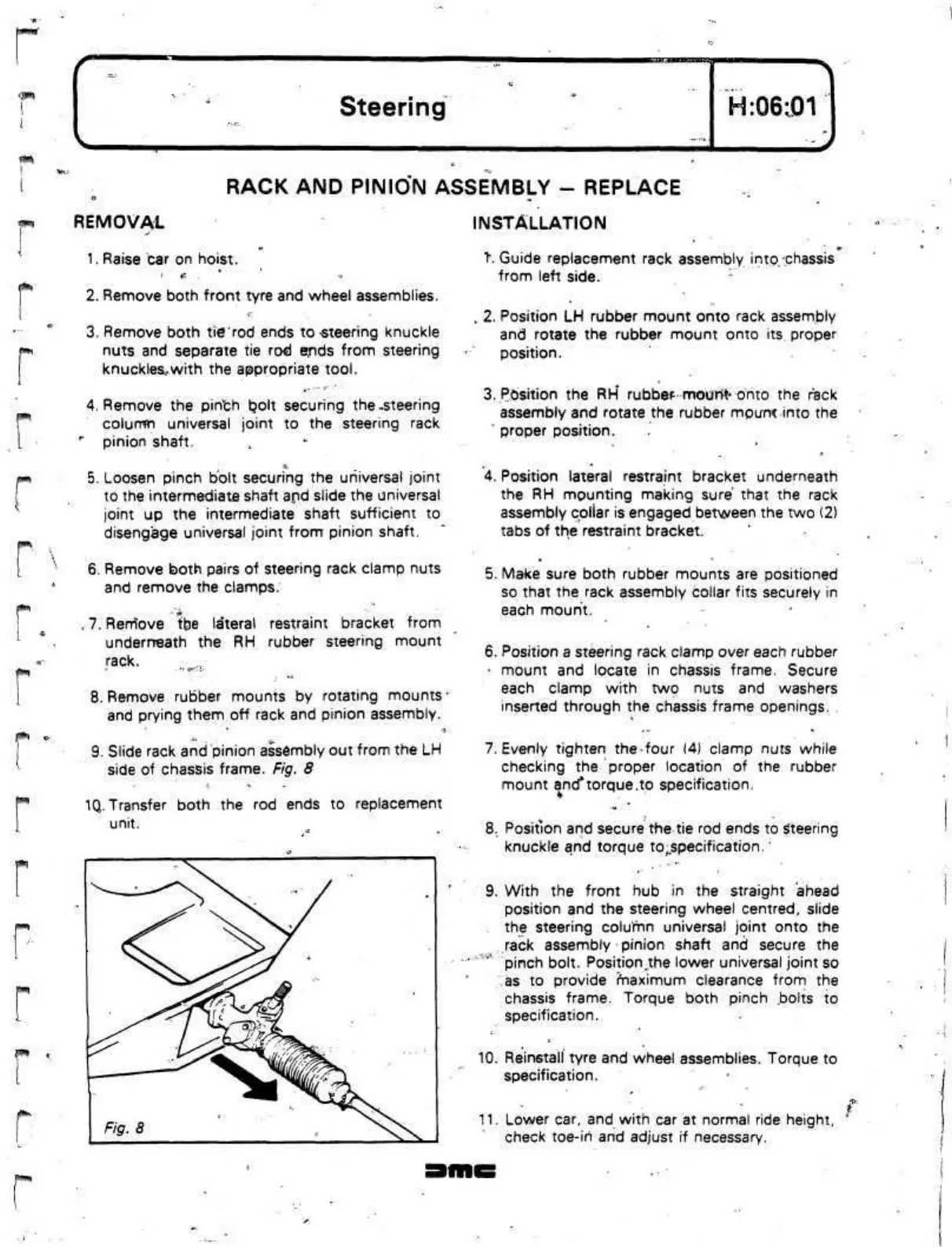
9. Slide rack and pinion assembly out from the LH
side of chassis frame. Fig. 8
1Q.
Transfer both the rod ends to replacement
unit.
t.
Guide replacement rack
assembly
into,
chassis
from left side.
:
t
2. Position LH rubber mount onto rack assembly
and rotate the rubber mount onto
its
proper
position.
3.
Position the
RH*
rubbef
mourft>
onto the rack
assembly and rotate the rubber
mpunc
into the
proper position.
4.
Position lateral restraint bracket underneath
the RH mounting making sure that the rack
assembly collar is engaged between the two (2)
tabs of the restraint bracket.
5. Make sure both rubber mounts are positioned
so that the rack assembly collar fits securely in
each mount.
6. Position a steering rack clamp over each rubber
•
mount and locate in chassis frame. Secure
each clamp with two nuts and washers
inserted through the chassis frame openings.
7. Evenly tighten
the-four (4)
clamp nuts while
checking the proper location of the rubber
mount
and*torque.to
specification.
8.
Position and secure the tie rod ends to Steering
knuckle and torque
to„specification.'
9. With the front hub in the straight ahead
position and the steering wheel centred, slide
the steering column universal joint onto the
rack assembly pinion shaft and secure the
pinch bolt.
Position^the
lower universal joint so
as to provide maximum clearance from the
chassis frame. Torque both pinch
.bolts
to
specification.
10.
Reinstall tyre and wheel assemblies. Torque to
specification.
£
11.
Lower car,
and
with car at normal ride height,
check toe-in and adjust if necessary.
y J -iW«i
 Loading...
