M:04:04
7. Remove the nuts, washers and through bolts
(15).
8. Separate the drive end bracket (8) from the
stator
(7),
slip ring end bracket (6) and rotor
assembly (16). Withdraw the stator (7) from
the slip ring end bracket (6).
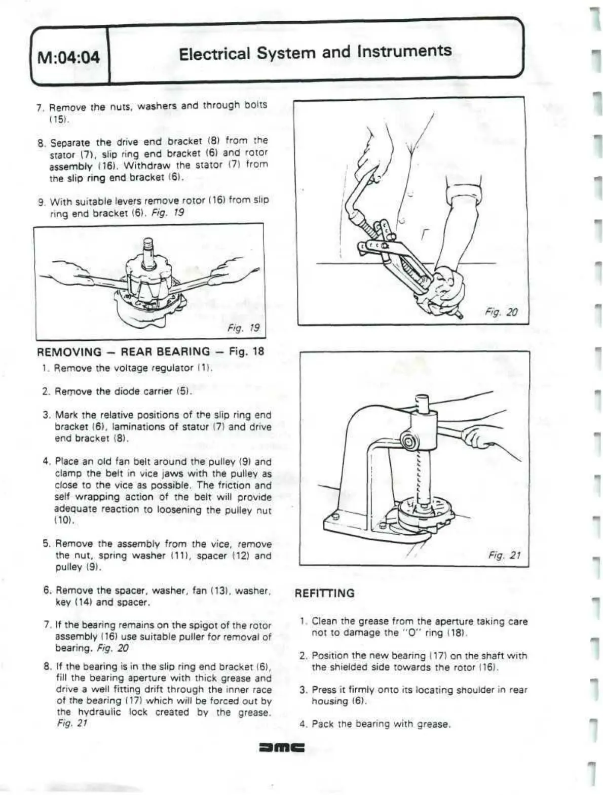
9. With suitable levers remove rotor (16) from slip
ring end bracket (6). Fig.
19
REMOVING
-
REAR BEARING - Fig. 18
1.
Remove the voltage regulator (1).
2.
Remove the diode carrier (5).
3. Mark the relative positions of the slip ring end
bracket (6), laminations of stator (7) and drive
end bracket (8).
4.
Place an old fan belt around the pulley (9) and
clamp the belt in vice jaws with the pulley as
close to the vice as possible. The friction and
self wrapping action of the belt will provide
adequate reaction to loosening the pulley nut
(10).
5. Remove the assembly from the vice, remove
the nut, spring washer (11), spacer (12) and
pulley (9).
6. Remove the spacer, washer, fan (13), washer,
key (14) and spacer.
7. If the bearing remains on the spigot of the rotor
assembly (16) use suitable puller for removal of
bearing.
Fig. 20
8.
If
the bearing is in the slip ring end bracket (6),
fill the bearing aperture with thick grease and
drive a well fitting drift through the inner race
of the bearing (17) which will be forced out by
the hydraulic lock created by the grease.
Fig.
21
REFITTING
1.
Clean the grease from the aperture taking care
not to damage the "0" ring (18).
2.
Position the new bearing (17) on the shaft with
the shielded side towards the rotor (16).
3. Press it firmly onto its locating shoulder in rear
housing (6).
4.
Pack the bearing with grease.
1
 Loading...
