N
.03:02
Heating and Air Conditioning
COMPONENT DESCRIPTION
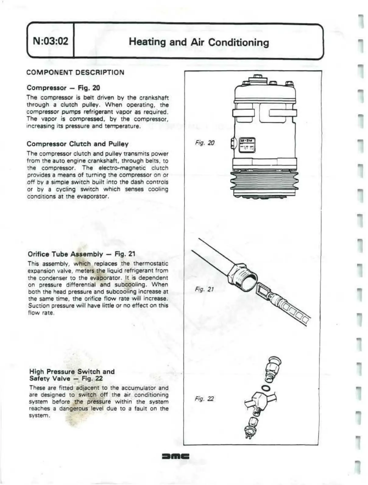
Compressor — Fig. 20
The compressor is belt driven by the crankshaft
through a clutch pulley. When operating, the
compressor pumps refrigerant vapor as required.
The vapor is compressed, by the compressor,
increasing its pressure and temperature.
Compressor Clutch and Pulley
The compressor clutch and pulley transmits power
from the auto engine crankshaft, through belts, to
the compressor. The electro-magnetic clutch
provides a means of turning the compressor on or
off by a simple switch built into the dash controls
or by a cycling switch which senses cooling
conditions at the evaporator.
Orifice Tube Assembly —
Rg.
21
This assembly, which replaces the thermostatic
expansion valve, meters the liquid refrigerant from
the condenser to the evaporator. It is dependent
on pressure differential and subcooling. When
both the head pressure and subcooling increase at
the same time, the orifice flow rate will increase.
Suction pressure will have little or no effect on this
flow rate.
High Pressure Switch and
Safety Valve —
Fig.
22
These are fitted adjacent to the accumulator and
are designed to switch off the air conditioning
system before the pressure within the system
reaches a dangerous level due to a fault on the
system.
Fig. 20
Fig.
21
Fig. 22
 Loading...
