Fuel,
Emission and Exhaust System
D:01:07
p
5
*!
pw^
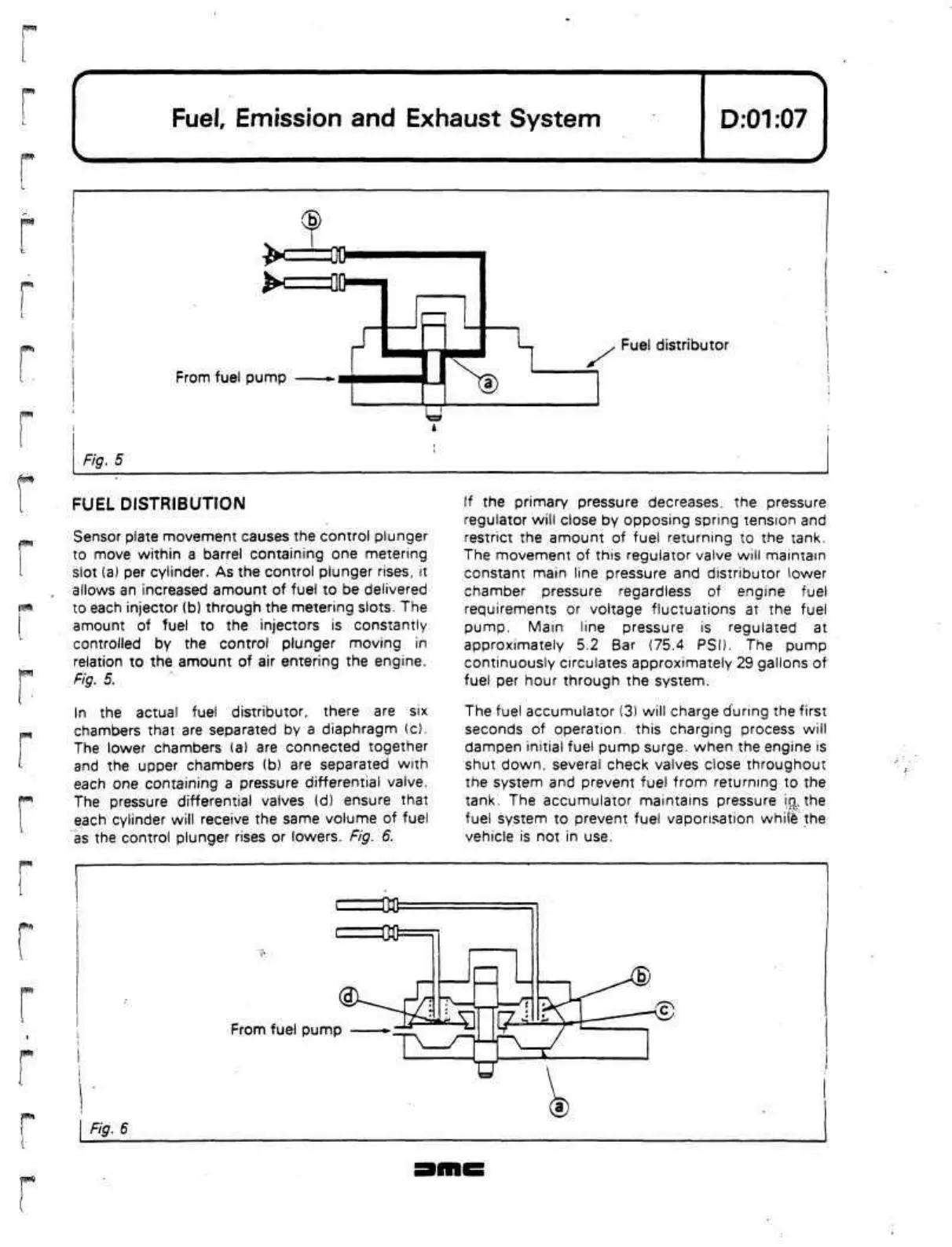
From fuel pump
Fig. 5
Fuel distributor
r
FUEL DISTRIBUTION
Sensor plate movement causes the control plunger
to move within a barrel containing one metering
slot (a) per cylinder. As the control plunger rises,
it
allows an increased amount of fuel to be delivered
to each injector (b) through the metering slots. The
amount of fuel to the injectors is constantly
controlled by the control plunger moving in
relation to the amount of air entering the engine.
Fig. 5.
In
the actual fuel distributor, there are six
chambers that are separated by a diaphragm (c).
The lower chambers (a) are connected together
and the upper chambers (b) are separated with
each one containing a pressure differential valve.
The pressure differential valves
(d)
ensure that
each cylinder will receive the same volume of fuel
as the control plunger rises or lowers. Fig. 6.
If
the primary pressure decreases, the pressure
regulator will close by opposing spring tension and
restrict the amount of fuel returning to the tank.
The movement of this regulator valve will maintain
constant main line pressure and distributor lower
chamber pressure regardless of engine fuel
requirements or voltage fluctuations at the fuel
pump.
Main
line pressure is regulated at
approximately 5.2 Bar (75.4 PSD. The pump
continuously circulates approximately 29 gallons
of
fuel per hour through the system.
The fuel accumulator (3) will charge during the first
seconds of
operation,
this charging process will
dampen initial fuel pump
surge,
when the engine is
shut
down,
several check valves close throughout
the system and prevent fuel from returning to the
tank. The accumulator maintains pressure
ifjLthe
fuel system to prevent fuel vaporisation
white*
the
vehicle is not in use.
From fuel pump
Fig. 6
 Loading...
