- 2 -
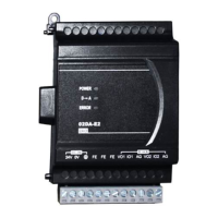
!External Wiring!
VO1
IO1
AG
VO4
IO4
AG
0V
24V
DC/DC
+15V
-15V
AG
FE
FE
CH1
CH1
Isolation wire*1
-10V~+10V
*2
*3
0mA~20mA
DC24V
CH4
CH4
[ Figure 3 ]
Voltage output
AC drive, recorder,
scale value...
AC drive, recorder,
scale value...
Current output
Isolation wire*1
Te r mi n al o f
power module
System
grounding
Class 3 grounding (100 or less)
converter
!
Note 1: Please isolate analog output and other power wiring.
Note 2: If noise interferes from loaded input wiring terminal is significant, please connect a capacitor
with 0.1 ~ 0.47ȝF 25V for noise filtering.
Note 3: Please connect
power module terminal and analog output module terminal to system
earth point and make system earth point be grounded or connects to machine cover.
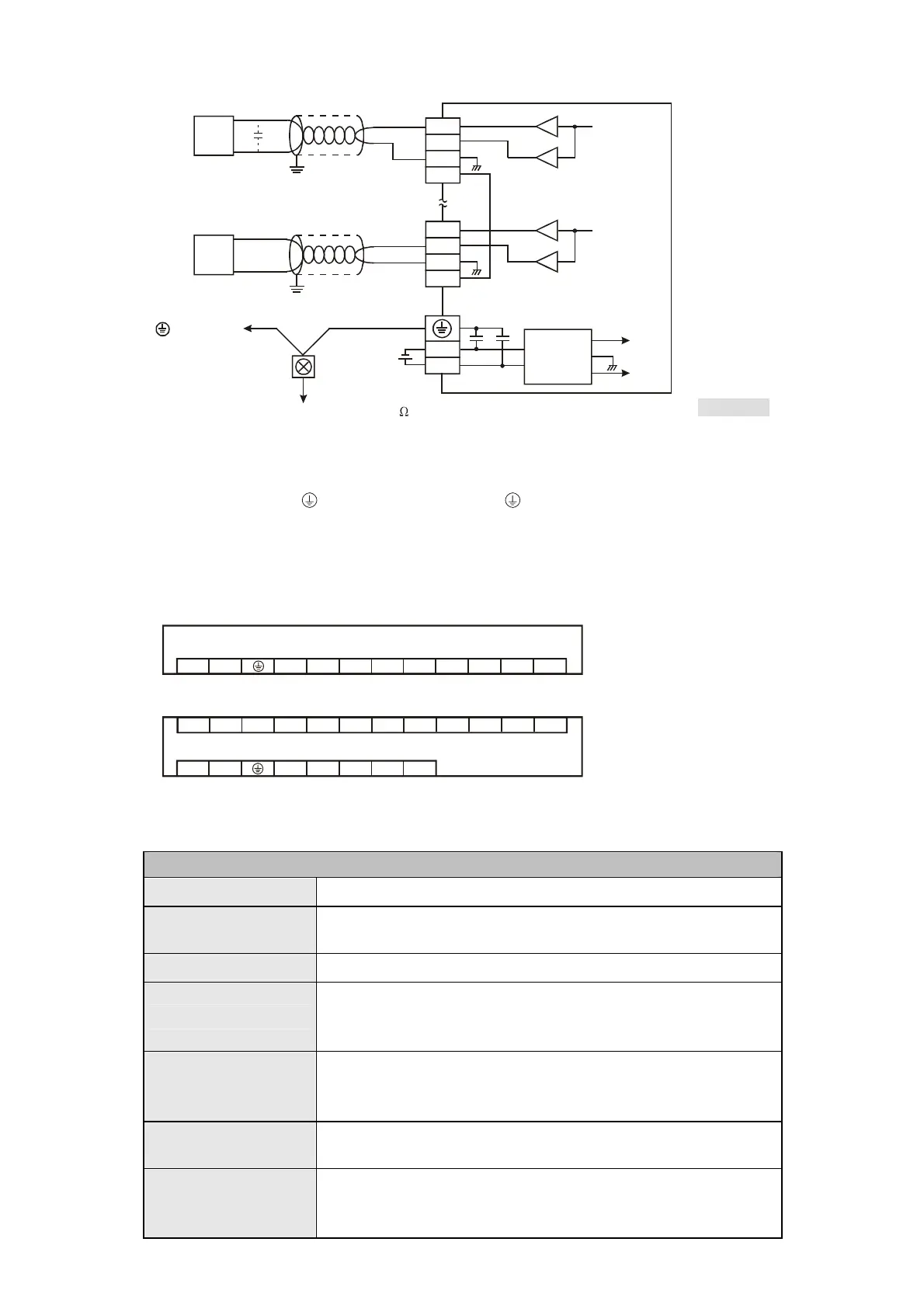
I/
O Terminal Layout
y DVP02DA-E2
FEFEFE0V24V
DVP02DA-E2 (2AO)
GIO2VO2AGIO1VO1
y DVP04DA-E2
IO4VO4FE0V24V
DVP04DA-E2 (4AO)
FEAG
IO2VO2FEAGIO1VO1
FEAGIO3VO3FEAG
Electrical Specifications
Digital/Analog module (02D/A & 04D/A)
Power supply voltage 24VDC (20.4VDC ~ 28.8VDC) (-15% ~ +20%)
Max. rated power
consumption
02DA: 1.5W, 04DA: 3W, supply by external power source.
Connector European standard removable terminal block (Pin pitch: 5mm)
Protection
Voltage output is protected by short circuit. Short circuit lasting for
too long may cause damage on internal circuits. Current output can
be open circuit.
Operation/storage
temperature
Operation: 0°C~55°C (temperature), 50~95% (humidity), Pollution
degree2
Storage: -25°C~70°C (temperature), 5~95% (humidity)
Vibration/shock
immunity
International standards: IEC61131-2, IEC 68-2-6 (TEST Fc)/
IEC61131-2 & IEC 68-2-27 (TEST Ea)
Series connection to
DVP-PLC MPU
The modules are numbered from 0 to 7 automatically by their
distance from MPU. Max. 8 modules are allowed to connect to MPU
and will not occupy any digital I/O points.
 Loading...