#4 H4162
╳
R/W instruction Instruction, factory setting: K0
CR#4 ‘0’(Off) ‘1’ (On)
b0 Count is disabled Count is enabled
b1
YH0 output is
disabled
YH0 output is enabled
b2
YH1 output is
disabled
YH1output is enabled
b3
YH0 and YH1
activate
independently
YH0 and YH1 affect
each other (they
cannot be ON/OFF
simultaneously)
b4 Preset disabled Preset is enabled
b5~b7 Reserved
b8 Not used Clear error flag
b9 Not used Clear YH0 output
b10 Not used Clear YH1 output
b11 Not used YH0 output setting
b12 Not used YH1 output setting
b13~b15 Reserved
1. When b0 is set to 1 and terminal “DIS” is off, count
is enabled.
2. When b1 is set to 1, YH0 (hardware comparison
output) output is enabled.
3. When b2 is set to 1, YH1 (hardware comparison
output) output is enabled.
4. When b3 is set to 1, YH0 and YH1 affect each
other (they cannot be ON/OFF simultaneously). In
other words, when YH0=ON, YH1 must be OFF
and when YH0=OFF, YH1 must be ON. When
b3=0, YH0 and YH1 activate independently.
5. When b4=0, terminal “PRE” is disabled.
6. When b8=1, all error flags (CR#29) will be cleared.
7. When b9=1, YH0 output will be cleared to be OFF.
8. When b10=1, YH1 output will be cleared to be
OFF.
9. When b11=1, YH0 output will be ON.
10.When b12=1, YH1 output will be ON.
Setting notes:
1. After setting CR#4, b8~b12 will be cleared to 0.
2. It needs to set to disable count(b0=0) before setting count mode (CR#5).
#5 H4163
╳
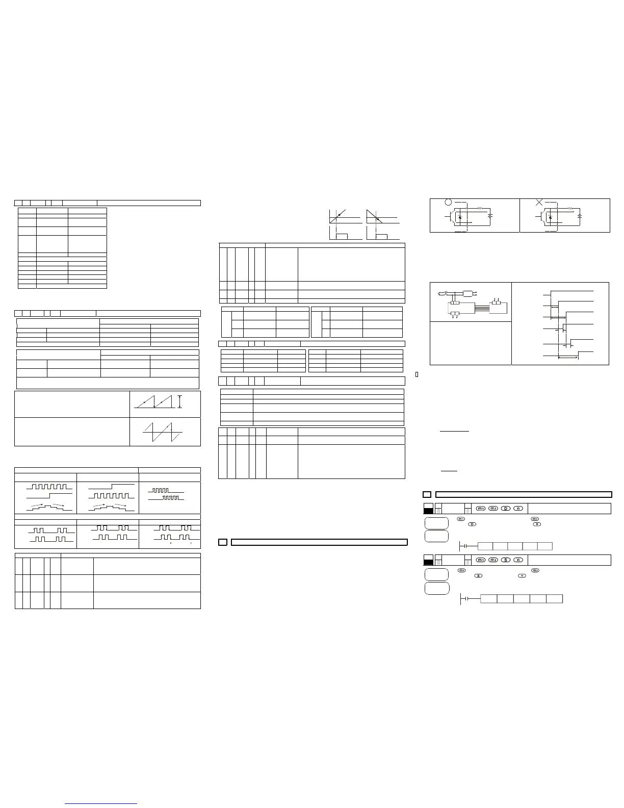
R/W Count mode setting Count mode K0~K11, factory setting is K0
Count mode CR#5 settings
32 bits 16 bits
2-phase 2 inputs Normal frequency K0 K1
Double frequency K2 K3
Four times frequency K4 K5
1-phase 2 inputs K6 K7
Count mode CR#5 settings
32 bits 16 bits
1-phase 1 input
Count Up/Down is controlled
by Hardware (Note 1)
K8 K9
Count Up/Down is controlled
by software (Note 2)
K10 K11
Note1: count up/down control is controlled by external input control.
Note2: count up/down control is controlled by internal control register(CR#1).
16-bit mode
When it is 16-bit mode, the count values are all positive value and its
range is 0~65,536. When overflow event is occurred, count value will
be changed from upper limit to 0 or from 0 to upper limit. The upper
limit is set by CR#3 and CR #2.
0
CR#3, #2
count length
32-bit mode
When it is 32-bit mode, the count range is -2,147,483,648 -
2,147,483,647. When overflow event is occurred, count value will
be changed from upper limit to lower limit or from lower limit to
upper limit. And upper limit is +2,147,483,647 and lower limit is
-2,147,483,648.
-2,147,483,648
+2,147,483,647
upper limit
lower limit
Setting notes:
1. It only can be written when count is disabled (bit 0 of CR#4 is 0).
2. After writing, it will initial controlled registers as follows: CR#1: 0. CR#2, 3: 65,536. CR#10: 0. CR#12, 13:
32,767. CR#14, 15: 32,767. CR#20, 21: 0. CR#22, 23: 0. CR#24, 25: 0.
1-phase 1 input (K8~K11) 1-phase 2 inputs (K6~K7)
External input count up/down control
(K8~K9)
Internal controlled register count
up/down control
1-phase 2 inputs counter (K6, K7)
count up
count down
Off ( )count up
On ( )count down
A i n p u t
B input
count
value
K0
K1
CR#1
A i n p u t
count
value
count up
count down
11220333
A i npu t
B inp ut
count value
pulse of count up
pulse of count down
2-phase 2 inputs (K0~K5)
Normal frequency (K0, K1) Double frequency (K2, K3) Four times frequency (K4, K5)
A i n p ut
B inp ut
count value
112002
A i n p u t
B input
count value
1122034 30
A i np ut
B inpu t
count value
1
3570
24
6
7
531
64
2
#6 ~ #9 Reserved
#11 #10 H4168 ╳ R/W Factory setting
Factory setting for counter (#10: Lower word / #11: Upper word),
factory setting: K0
Setting notes: in 16-bit mode, CR#11 will be cleared to 0 when
writing factory setting.
#13 #12 H416A ╳ R/W
YH0 comparison
value
YH0 output comparison value (#12: Lower word / #13: Upper
word), factory setting: K32,767.
Setting notes: in 16-bit mode, CR#13 will be cleared to 0 when
writing YH0 comparison value.
#15 #14 H416C ╳ R/W
YH1 comparison
value
YH1 output comparison value (#14: Lower word / #15: Upper
word), (factory setting: K32,767).
Setting notes: in 16-bit mode, CR#15 will be cleared to 0 when
writing YH1 comparison value.
When current value of counter = comparison value, output
YH0/YH1 will be ON and hold. User can clear output point by
using b9 and b10 of CR#4.
If count value = comparison value by using PRESET or
instruction TO, corresponding output YH0 or YH1 will be OFF. In
other case that count value = comparison value does not use
PRESET or instruction TO, corresponding output YH0 or YH1 will
be ON.
CR#4
b9, b10 SET
CR#4
b9, b10 SET
current value
of counter
Comparison
value
Comparison
value
current value
of counter
current value
of counter
current value
of counter
#16~ #19 Reserved
#21 #20 H4172 ╳ R/W
Current value of
counter
Current value of counter (#20: Lower word / #21: Upper word),
factory setting is K0.
Setting notes:
it must write with 32-bit.
In 16-bit mode, value that is written must be less than ring
length (CR#2).
In 16-bit mode, CR#21 will be cleared to 0 when writing into
current value of counter.
#23 #22 H4174 ╳ R/W Max. count value
Max. count value (#22: Lower word / #23: Upper word), factory
setting is K0.
#25 #24 H4176 ╳ R/W Min. count value
Min. count value (#24: Lower word / #25: Upper word), factory
setting is K0.
#26 H4178 ╳ R Comparison result Comparison result
CR#26 ‘0’(Off) ‘1’(On) CR#26 ‘0’(Off) ‘1’(On)
b2
Setting value≦
current value
Setting value >
current value
b6
Setting value≦
current value
Setting value > current
value
b1
Setting value≠
current value
Setting value =
current value
b5
Setting value≠
current value
Setting value = current
value
YH0
b0
Setting value≧
current value
Setting value <
current value
YH1
b4
Setting value≧
current value
Setting value < current
value
#27 H4179
○
R Action status The indication of count up/down and terminal status
CR#27 ‘0’(Off) ‘1’(On) CR#27 ‘0’(Off) ‘1’(On)
b0 - Count up b4 PRE input is Off PRE input is On
b1 - Count down b5 DIS input is Off DIS input is On
b2 A input is off A input is on b6 YH0 output is Off YH0 output is On
b3 B input is off B input is on b7 YH1 output is Off YH1 output is On
#29 H417B
╳
R/W Error status
Data register that is used to save all error status. Refer to
table below.
CR#29 Error Status
b0~ b3 Reserved
b4 CR number that is designated by instruction FROM/TO exceeds the usage range
b5
Overflow indication, When count-up value exceeds upper limit(upper limit is CR#2 and #3
in 16-bit mode and it is K2,147,483,647 in 32-bit mode)
b6
Overflow indication, When count-down value is less than lower limit(lower limit is 0 in
16-bit mode and it is K-2,147,483,648 in 32-bit mode)
b7~ b15 Reserved
#30 H417C ○ R System version
Hexadecimal, display current software version, such as version
1.0A will be displayed as H’010A.
#31 H417D ○ R/W
Communication
address
RS-485 communication address, range set: 01~255, factory
default value: K1
#32 H417E ○ R/W
Baud Rate
Setting
Baud rate setting: 4800,9600,19200bps,38400 bps,57600 bps,
115200 bps. ASCII mode data format is always 7Bit, even bit,
and 1 stop bit (7 E 1). RTU mode data format is always 8Bit,
even bit , and 1 stop bit ( 8 E 1)
b0: 4800 bps(bit/sec.), b1: 9600 bps(bit/sec.) (default value)
b2: 19200 bps(bit/sec.), b3: 38400 bps(bit/sec.)
b 4: 57600 bps(bit/sec.), b 5: 115200 bps(bit/sec.)
b6~b14: reserved, b15: ASCII / RTU mode switch
CR#0~CR#34: The corresponding addresses are H 415E-H 4180 for user to read/write by
using RS-485.
1. Baud rate could be 4800, 9600, 19200, 38400 and 57600bps.
2. Communication protocol can be Modbus ASCII mode and RTU mode. For ASCII mode, data
format is 7Bits, even, 1 stop bit (7 E 1). For RTU mode, data format is 8Bits, even, 1 stop bit
(8 E 1).
3. Function code: 03H: read register data. 06H: write one WORD data into register. 10H: write
multiple WORDs into register.
5 TRIAL RUN & TROUBLESHOOTING
MPU connects to HC extension module
1. Make sure that the power of MPU and extension unit is OFF before wiring.
2. Open extension port of EH MPU and connect to HC extension unit with cable. There is no
connection order for EH MPU to connect extension unit, mix connection is allowed.
3. The power supply of HC extension unit must be external +24VDC power supply.
4. Before power up, check if the load circuit of output points YH0 and YH1 is correct, especially
the circuit between YH0+, YH0- and YH1+, YH1-. There is a Zener Diode that is connected
between YH0+, YH0- and YH1+, YH1- in HC. If the positive/negative pole is wrong, it may
cause unexpected result.
YH0+
YH1+
YH1-
YH0-
DC 5~24VDC
Load
YH0+
YH1+
YH1-
YH0-
DC 5~24VDC
load
5. Before power up, check if A phase or B phase connects to correct voltage level. (there are
three voltage level: +24, +12V and +5V) If +24V signal connects to +5V input terminal, it may
damage internal circuit.
6. After power up MPU, it will start to detect extension module. If no external +24VDC power is
applied to HC at this time or power is applied after EH MPU completing detecting extension
module, the connection will fail. Therefore, power wiring and power supply timing should be
as following.
Power wiring
85~264VAC
AC/DC
+24V_EXT
+24V_IN T
01HCEH MPU
+24V input
LNG
+24V 24G
+24V
0V
Power supply
Timing analysis
When power supply for HC is +24V_INT:
t5>t3, power is ON and the connection of HC
extension unit is normal.
When power supply for HC is +24V_EXT:
Because start time (t2) of external power supply
for HC extension module is unknown, user must
make sure that t2+t4 < t1+t5, otherwise HC
extension module cannot be detected by MPU.
Power supply timing
+24V_INT
+24V_EXT
t1
t2
t3
t4
t5
t1:1~2 seconds
t2:1~3 seconds
t3:0.5~1 second
 Loading...