EasyManuals Logo
Home>Delta Electronics>Monitor>Network Device DOP-B

Delta Electronics Network Device DOP-B User Manual

Delta Electronics Network Device DOP-B
43 pages
To Next Page IconTo Next Page
To Previous Page IconTo Previous Page
Page #9 background imageLoading...
Page #9 background image
English-8
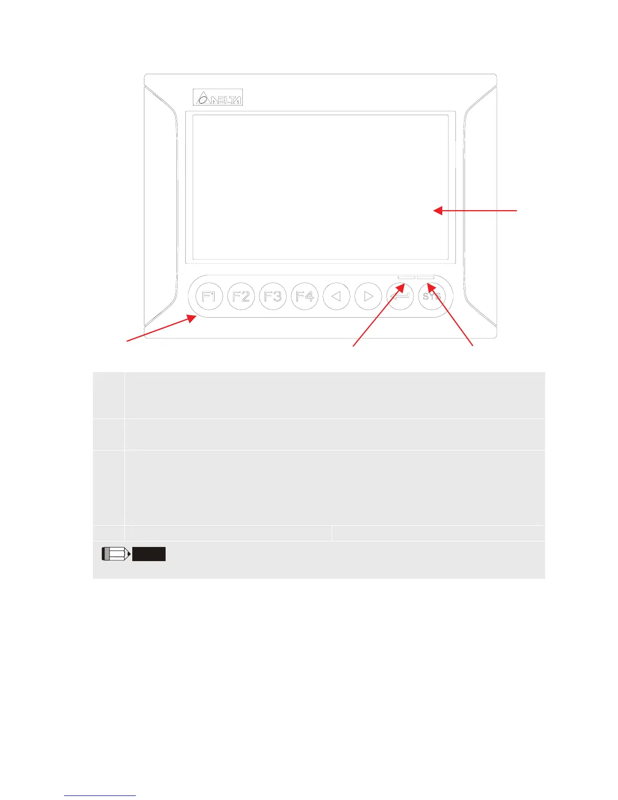
DOP-B07S200 / DOP-B07S201 / DOP-B07E205 (Front View)
A
User-defined Function Keys / System Keys
User-defined Function Keys: F1, F2, F3, F4
System Keys: Y, Z, , SYS
B
Power LED Indicator (Green)
Lights in green when HMI works normally.
C
Left side: Operation LED Indicator (Blue)
The operation LED indicator blinks in blue when either the communication is carried
out or the data is accessing (please refer to the ‘Note’ below for explanation).
Right side: Alarm LED Indicator (Red)
The alarm LED indicator blinks in red when one of the alarms is on.
D Touch Screen / Display
NOTE
The definition of the operation LED indicator (Blue) can be determined by the users freely.
CB
A
D

Questions and Answers:

Question and Answer IconNeed help?

Do you have a question about the Delta Electronics Network Device DOP-B and is the answer not in the manual?

Delta Electronics Network Device DOP-B Specifications

General IconGeneral
BrandDelta Electronics
ModelNetwork Device DOP-B
CategoryMonitor
LanguageEnglish

Related product manuals