16
6.4 AC and DC Cabling Instructions
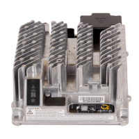
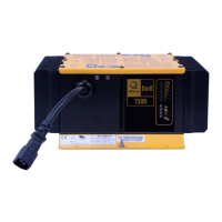
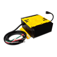
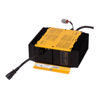
AC and DC cabling for the IC650 Charger can be completely customized by the customer. Cables can
easily be attached into the sealed DC block and the IEC320 AC receptacle.
The modular design of the IC650 Charger has several benefits:
Customers only have to manage a single SKU for each power level (e.g. 24V / 36V / 48V).
Units can be customized by the customer at their factory based on demand for specific DC
connectors or AC cords for different countries.
AC and DC cables are field replaceable, saving the time and expense of sending units for repair.
When supplied with cables, field technicians can test and operate the charger in only a few
minutes.
DC Cabling Installation Instructions
To attach DC cabling to the IC650 Charger, you
will need the following items:
1 - Torx T30 screwdriver
1 - Torx T10 screwdriver
2 - Torx T30 / M6 screws
2 - Torx T10 screws
1 - DC cable with ring terminals for
attachment into the DC block
1 - Delta-Q IC650 DC block cover (part no.
_____)
1 - Delta-Q IC650 DC cable clamp (part no.
_____)
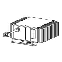
1. Remove the DC block cover.
2. Attach the DC cable clamp over the DC cable,
then attach positive and negative leads from the
DC cable to the positive and negative terminals
inside the DC block. Reattach the DC block cover.
Figure 16. Remove the DC block cover by inserting
the head of the Torx T30 screwdriver into the gap
on the lower left side of the DC block xture, and
apply pressure to trigger the cover’s release. It can be
removed and put aside.
Figure 17. Fix the DC cable in place using the Delta-Q
cable clamp, fastened with Torx T10 screws to a
recommended torque of 0.6Nm +/-6%. Proceed by
attaching the positive and negative leads to the
positive and negative terminals, respectively, using
the Torx T30 screwdriver and Torx T30 / M6 screws,
with a recommended torque of 4.5Nm +/-5%.
 Loading...