Chapter 2 Specifications and System Configuration
2-29
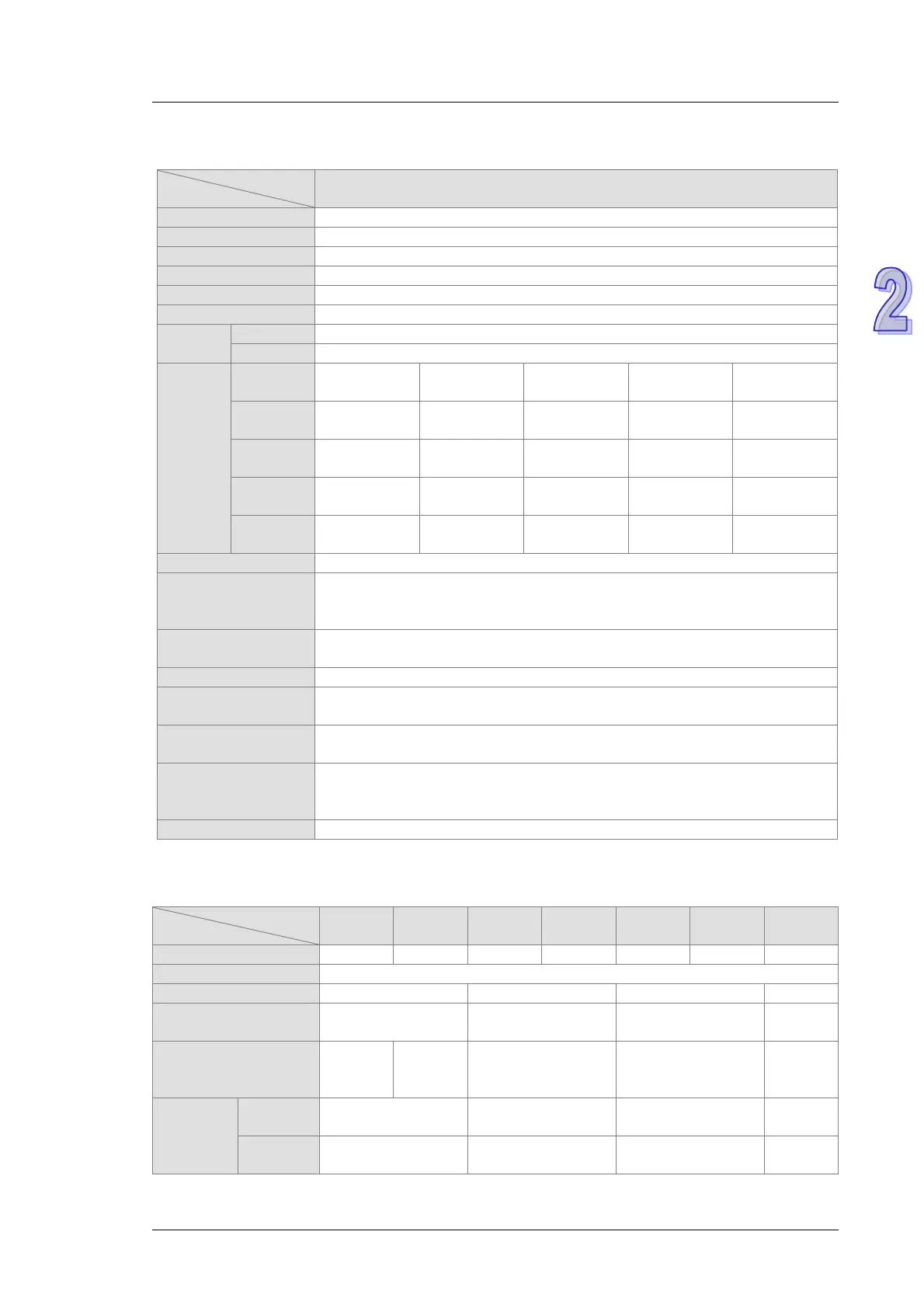
Electrical specifications for the inputs on a digital input/output module which supports I/O
interrupts (The signals passing through the inputs are 24 VDC signals.)
Model
16AR10N-5A
Direct current (sinking or sourcing)
time
0.1 ms 0.5 ms 3 ms 15 ms 20 ms
OFF→ON
0.11 ms 0.51 ms 3.01 ms 15.01 ms 20.01 ms
0.12 ms 0.52 ms 3.02 ms 15.02 ms 20.02 ms
ON→OFF
0.11 ms 0.51 ms 3.01 ms 15.01 ms 20.01 ms
0.15 ms 0.55 ms 3.05 ms 15.05 ms 20.05 ms
Input signal
Sinking: The inputs are NPN transistors whose collectors are open collectors.
Sourcing: The inputs are PNP transistors whose collectors are open collectors.
Electrical
Optocoupler; 500VAC
When the optocoupler is driven, the input LED indicator is ON.
Trigger for an interrupt
An interrupt is triggered when there is a transision in a signal from low to
high/from high to low/from low to high or from high to low.
Interrupt service
routine
The interrupt service routine numbers which can be set are in the rangeof 0 to 31.
Filtering cycle which
can be set for an input
channel
0.1 ms, 0.5 ms, 3 ms (default), 15 ms, or 20 ms
Electrical specifications for the outputs on digital input/output modules
AH16AN01R
AH16AP11R
AH16AN01T
AH16AP11T
AH16AN01P
AH16AP11P
AH16AN01S
Voltage specifications
250 VAC, and below
30 VDC
12~30 VDC
*2
12~30 VDC
*2
Electrical
isolation/Voltage
Opto-
coupler;
Relay;
500VAC
Opto-coupler; 500VAC
Opto-coupler; 500VAC
Opto-
coupler;
Maximum
load
Resistance
0.5 A/output
Inductance Life cycle curve
*3
12 W (24 VDC) 12 W (24 VDC)
Not

 Loading...


