KNOW YOUR COMPOUND MITER SAW
Refer to Figure 1.
Using this tool safely requires that you understand the
information provided in this operator’s manual, as well
as the project you are attempting. Before using this
product, familiarize yourself with all operating features
and safety rules.
A.
14-amp motor with all ball bearings and externally
accessible brushes for ease of servicing.
B.
when making all cuts.
C.
workpiece and provides a safe working surface.
D.
the saw at desired miter angles.
E.
at the rear of the saw and controls bevel settings.
It also rotates the head with the base during miter
cuts.
F.
stops have been provided at 0°, 15°, 22-1/2°, 31.6°,
and 45°. The blade stops have been provided on
both the left and right side of the miter table.
G.
clamp helps to position and secure the workpiece
to the fence, ensuring safer operation and more
accurate cuts.
H. BASE: Supports the tool and features mounting
holes.
I.
the tool to a stable surface.
wrench features a Phillips screwdriver at one
end and a hex key at the other. Use the hex key
when installing or removing blade and the Phillips
screwdriver when removing or loosening screws.
When not in use, the wrench can be stored in the
base of the saw.
K.
table provides a level and sturdy work surface.
L.
desired angle for bevel cuts. There are positive stop
7
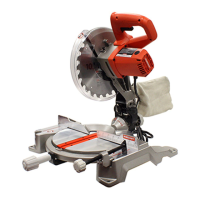
FIGURE 1
(features move clockwise around tool)
A. Motor
B. Fence
C. Throat Plate
D. Miter Lock
E. Miter Control Arm
F. Miter Gauge with Positive Stops
G. Horizontal Work Clamp
H. Base
I. Mounting Holes
J. On-Board Wrench
K. Work Table
L. Bevel Lock
M. Dust Bag
N. Upper and Lower Blade Guards
O. Blade (not visible)
P. Trigger Switch
Q. Spindle Lock
R. Electric Brake (not shown)
S. Laser Guide (not shown)
A
Q
P
O
N
C
B
F
D
E
G
H
I
K
L
M
J
1
2
3
4
5
6
7
FEATURES
 Loading...