
C
Colleen GrahamAug 2, 2025
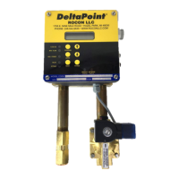
What to do if my DeltaPoint Manifold DPM-12GM-6-P1A-FP10-F-V1 restarts and shows flow briefly, then proceeds to shutdown?
- NNicholas HumphreyAug 2, 2025
If your DeltaPoint Portable Generator restarts, briefly shows flow, and then shuts down, there are two potential causes: 1. The PROFINET shutoff bit hasn't been reset by the server. 2. The return sensor is affected by debris or is malfunctioning. To resolve this, refer to “COMPARISON TESTING” and “SUPPLY FLOW IS GREATER THAN RETURN FLOW”. If either sensor is misreading, first flush the Bluffs, then work on sensors.