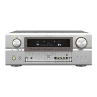
q
Input signal indicator
The respective indicator will light corresponding to
the input signal.
w
Input signal channel indicator
The channels included in the input source will light.
This lights when the digital signal is inputted.
e
Information display
This displays the surround mode, function name or
setting value, etc.
r
Output signal channel indicator
The audio channels that can be output light.
t
Speaker indicator
This lights corresponding to the settings of the
surround speakers of the various surround modes.
y
Decoder indicator
This lights when each decoder is operating.
u
Master volume indicator
This displays the volume level.
The Setup item number is displayed in System
Setup.
i
IEEE1394 indicator
This lights during playback in a IEEE1394
connection.
o
Multi (zone) indicator
ZONE3 mode is selected in ZONE3/REC SELECT.
!0
Recording output source indicator
REC OUT mode is selected in ZONE3/REC
SELECT.
!1
DENON LINK indicator
This lights during playback in a DENON LINK
connection.
!2
AL24 indicator
The AL24 indicator lights when the PURE DIRECT,
DIRECT, STEREO, MULTI CH PURE DIRECT,
MULTI CH DIRECT, MULTI CH IN mode is selected
in the PCM input signal.
!3
Input mode indicator
This lights corresponding to the setting of the input
mode.
Remote control unit
For details on the functions of these parts, refer to the pages given in parentheses ( ).
Mode selector buttons
.................................(20, 32)
Input source button
.................................(20, 32)
Surround mode button
.................................(20, 32)
System buttons...(32 ~ 35)
System buttons ...........(39)
Power buttons ...............(9)
Tuner system buttons
.......................................(33)
ROOM EQ button ........(22)
SYSTEM SETUP button
.........................................(9)
System buttons...(32 ~ 35)
Tuner system buttons
.......................................(32)
VIDEO SELECT button
.......................................(21)
Input mode selector
buttons....................(21, 22)
Remote control signal
transmitter......................(3)
Number/SYSTEM CALL
button......................(20, 32)
Cursor buttons...............(9)
ON SCREEN button
.................................(21, 25)
CH SELECT/ENTER button
............................(9, 31, 32)
Master volume control
buttons....................(20, 39)
Muting button .......(21, 39)
SURROUND PARAMETER
button............................(24)
TEST TONE button......(55)
SPEAKER button ..........(21)
NOTE:
•With the AVC-A11XV, the “Z4”, “VCR4”, “AUX”, “RDS”, “M.SEL” and “SCALE” buttons cannot be used.
• The AVC-A11XV’s 7CH STEREO surround mode can be operated using the “9CH” button.
• For instructions on setting the remote control unit back light’s lighting time ( page 36).

 Loading...