EasyManua.ls Logo

Denon DN-961FA - Waveform and Output Level Adjustments

Denon DN-961FA
92 pages
Print Icon
To Next Page IconTo Next Page
To Previous Page IconTo Previous Page
Loading...
@
ON-95
1FA/961FA
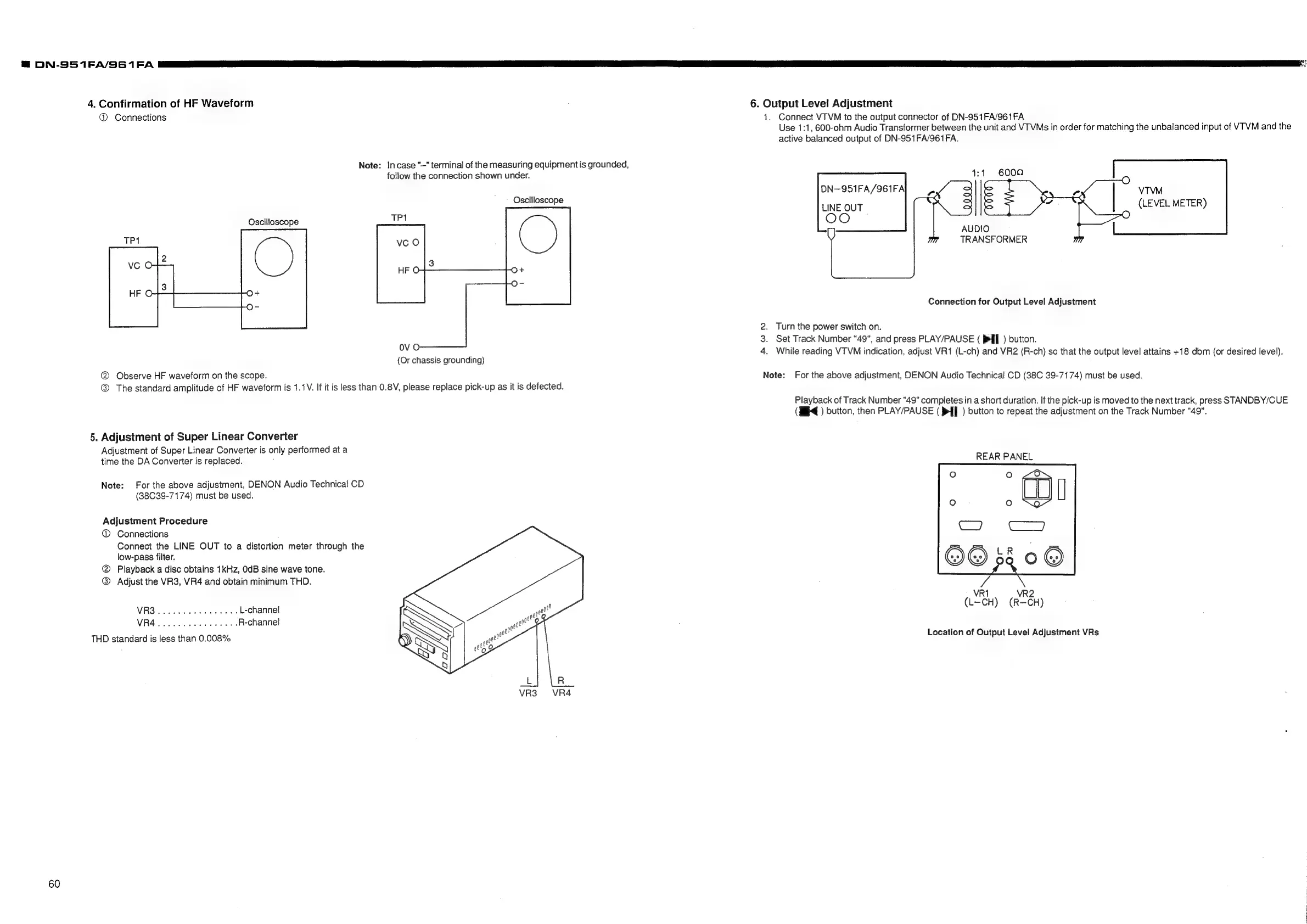
4.
Confirmation
of
HF
Waveform
@
Connections
Note:
Incase
"—"
terminal
of
the
measuring
equipment
is
grounded,
follow
the
connection
shown
under.
Oscilloscope
Oscilloscope
ovo
(Or
chassis
grounding)
@®
Observe
HF
waveform
on
the
scope.
@®
The
standard
amplitude
of
HF
waveform
is
1.1V.
If
it
is
less
than
0.8V,
please
replace
pick-up
as
it
is
defected.
5.
Adjustment
of
Super
Linear
Converter
Adjustment
of
Super
Linear
Converter
is
only
performed
at
a
time
the
DA
Converter
is
replaced.
;
Note:
For
the
above
adjustment,
DENON
Audio
Technical
CD
(38C39-7174)
must
be
used.
Adjustment
Procedure
@®
Connections
Connect
the
LINE
OUT
to
a
distortion
meter
through
the
low-pass
filter.
@
Playback
a
disc
obtains
1kHz,
OdB
sine
wave
tone.
@
Adjust
the
VR3,
VR4
and
obtain
minimum
THD.
VRS
irs
ok
aba
Pesaran
L-channe!
MRA
dbnestoreiacd
sbecre
wove
te
R-channel
THD
standard
is
less
than
0.008%
VR3
~=VR4
6.
Output
Level
Adjustment
1.
Connect
VTVM
to
the
output
connector
of
DN-951FA/961FA
Use
1:1,
600-ohm
Audio
Transformer
between
the
unit
and
VTVMs
in
order
for
matching
the
unbalanced
input
of
VTVM
and
the
active
balanced
output
of
DN-951FA/961FA.
4:1
DN-951FA/961FA\
LINE
OUT
OO
VTVM
(LEVEL
METER)
AUDIO
TRANSFORMER
Connection
for
Output
Level
Adjustment
2.
Turn
the
power
switch
on.
3.
Set
Track
Number
"49",
and
press
PLAY/PAUSE
(
>
)
button.
4.
While
reading
VTVM
indication,
adjust
VR1
(L-ch)
and
VR2
(R-ch)
so
that
the
output
level
attains
+18
dbm
(or
desired
level).
Note:
For
the
above
adjustment,
DENON
Audio
Technical
CD
(38C
39-7174)
must
be
used.
Playback
of
Track
Number
"49"
compietes
in
a
short
duration.
If
the
pick-up
is
moved
to
the
next
track,
press
STANDBY/CUE
(I4
)
button,
then
PLAY/PAUSE
(
>
)
button
to
repeat
the
adjustment
on
the
Track
Number
"49".
REAR
PANEL
VR1
VR2
(L-CH)
(R—CH)
Location
of
Output
Level
Adjustment
VRs