5
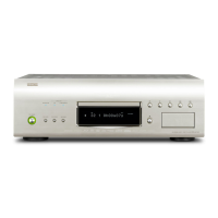
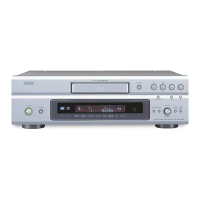
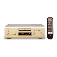
DVD-9000/DVD-A1
(a)
(b)
(a)
(e)
(d)
(c)
(e)
(d)
(c)
Top Cover
Side Cover
Side Cover
Inner Top Cover
(e’)
(d’)
(d’)
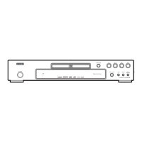
Front Panel Ass’y
Front Angle
[A]
[C]
[B]
2. Front Panel Ass'y/Front Angle
(1) Front Panel Ass'y
Remove 8 pcs of 3mm B-tight screw (d’), 4 pcs on the
top and bottom each, and pull out the Front Panel Ass'y
to the arrow direction.
[A]: Disconnect VH wire from [CY025] on the Power SW
P.W.B.
[B]: Disconnect PH wire from [CX041] on the Digital
Power P.W.B.
[C]: Disconnect FFC wire from [CX171] on the Main
P.W.B.
Detach the Front Panel Ass'y.
(2) Front Angle
Remove 4 pcs of 3mm B-tight screw (e’), and take out
the Front Angle upward.
DISASSEMBLY
( Follow the procedure below in reverse order when reassembling )
* Caution: Each edge inside of the metal parts may be "sharp edge", so be careful not to be injured when handling them.
Screwing torque : 1.6Nm for (a) and (d)
Screwing torque : 1.1Nm (unless otherwise specified)
1. Top/Side Cover
(1) Top Cover
Remove 8 pcs of 4mm S-tight screw (a) and 2 pcs of
3mm B-tight screw (b), then detach the Top Cover to the
arrow direction.
(2) Inner Top Cover
Remove 6 pcs of 3mm B-tight screw (c) and detach the
Inner Top Cover upward.
(3) Side Cover
Remove 4 pcs of 4mm special screw (d) and 4 pcs of
3mm B-tight screw (e) on both sides, then detach the
Side Cover upward. The Side Cover is commonly used
either left and right.
Screwing torque : 1.1Nm (unless otherwise specified)
 Loading...