2
DEOS AG
Birkenallee 76 ▪ 48432 Rheine ▪ Germany ▪
+49 5971 91133-0 ▪ +49 5971 91133-2999 ▪ info@deos-ag.com ▪ www.deos-ag.com
© DEOS AG 2015 ▪ Technische Änderungen und Irrtümer vorbehalten.
Datenblatt Revision 2 - Stand: 20.07.2015 Data sheet Revision 2 - Issue date: 20.07.2015
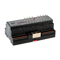
OPEN 600 EMS
Zubehör
Artikel Typ
DS-024095 DS-Bat OPEN EMS
Ersatzbatterie für OPEN EMS
DS-390024 DS-PKM
Koppelmodul mit Abschlusswiderstand
DS-390019 DS-BBS 10
Brückenbusstecker für OPEN IO Module
(1 VE = 10 Stück)
DS-390020 DS-BBS 100
Brückenbusstecker für OPEN IO Module
(1 VE = 100 Stück)
Sicherheitshinweis
Der Umgang mit diesem Gerät darf nur durch entsprechend
geschultes Personal erfolgen, das berechtigt ist, Arbeiten an
elektrischen Anlagen auszuführen.
Die Geräte dürfen nicht in Verbindung mit Geräten benutzt
werden, die direkt oder indirekt menschlichen, gesundheits- oder
lebenssichernden Zwecken dienen oder durch deren Betrieb
Gefahren für Menschen, Tiere oder Sachwerte entstehen können.
Das Gerät muss außer Betrieb gesetzt werden, wenn ein
gefahrloser Betrieb (z.B. sichtbare Beschädigungen) nicht mehr
gewährleistet ist. Der Garantieanspruch erlischt beim Öffnen des
Gerätes.
Elektrischer Anschluss
Die Geräte sind für den Betrieb an Kleinspannung ausgelegt.
Beim elektrischen Anschluss der Geräte sind die techn. Daten zu
berücksichtigen.
Die Geräte müssen bei einer konstanten Betriebsspannung
betrieben werden. Strom-/Spannungsspitzen beim Ein-/Ausschalten
der Versorgungsspannung müssen bauseits vermieden werden.
Die Versorgungs- und Signalleitungen müssen nach dem
aktuellen Stand der Technik angeschlossen und verlegt werden.
Insbesondere sind bei der Verlegung von Sensorleitungen mögliche
Störeinkopplungen durch parallel verlaufende Fremdleitungen zu
vermeiden.
Für die Verlegung der CAN-Bus Leitungen ist auf die Einhaltung der
Spezikationen für den Aufbau eines CAN-Bus-Systems zu achten.
Montagehinweise
Die Montage ist nach gültigen Installationsstandards durch
geschultes Personal auszuführen. Die Montage der Geräte erfolgt
auf Standard-(Norm) Hutschiene 35 mm in Schaltschränken.
Bei der Festlegung des Montageortes ist zu beachten, dass die
Grenzen der Betriebstemperatur nicht überschritten werden.
Für die Montage in Zwischendecken sind geeignete Gehäuse
vorzusehen. Nötigenfalls sind Revisionsöffnungen einzuplanen.
Bei der Montage ist darauf zu achten, dass die offenen Teile des
Gerätes frei von Verschmutzungen sind - insbesondere kann das
Gerät durch Eindringen von Metallspänen zerstört werden.
Hinweis:
Bei Verwendung von Schraubklemmen, darf das maximale
Anzugsmoment der Schraubklemmen 0,4 Nm nicht übersteigen.
Das Überschreiten des max. Anzugsmomentes kann zur Zerstörung
der Klemme führen. Dadurch kann der elektrische Kontakt an der
Klemme nicht mehr gewährleistet werden.
Accessory
Article Type
DS-024095 DS-Bat OPEN EMS
Spare battery for OPEN EMS
DS-390024 DS-PKM
Coupler module with terminating resistor
DS-390019 DS-BBS 10
Bridge bus connector for OPEN IO modules
(1 PU = 10 pieces)
DS-390020 DS-BBS 100
Bridge bus connector for OPEN IO modules
(1 PU = 100 pieces)
Safety guidelines
Handling with this equipment may take place only through trained
personnel, who is entitled to implement work on electrical system.
The devices may not be used in connection with devices which
serve directly or indirectly human health or life-securing purposes or
which can arise danger for humans, animals or material assets.
The device must be set out of service, if a safe operation (e.g.
visible damages) is no longer possible. With an interference into the
equipment the warranty claim expires!
Electric connection
The devices are appropriate for the operation at low voltage.
During the electrical connection of the devices, the technical data of
the devices are valid.
The devices must be operated during a constant operating voltage.
Current/voltage peaks when switching on/off of the supply voltage
must be avoided on site.
The supply- and signal lines must be connected and laid according
the current state of the art. In particular possible interference
couplings have to be avoided by parallel running foreign lines with
the transfer of sensor lines.
For the transfer of the CAN-bus lines it is important to pay attention
to the adherence of the specications for the structure of a CAN-
bus system.
Mounting advices
The assembly is to be implemented after installation standards
by trained personnel. The assembly of the devices takes place on
standard (norm) DIN rail 35 mm in cabinets.
When dening the assembly place it should be noted that the
borders of the operating temperatures are not exceeded.
For the assembly in intermediate ceilings suitable housings have to
be planned. If necessary, inspection openings have to be planned.
When assembling it is important to be certain, that the open parts
of the device are free from pollution - in particular the device can be
destroyed by penetration of metal chips.
Note:
By using screw terminals the maximum torque of the screw
terminals may not exceed 0.4 Nm. The exceeding of the max.
torque can lead to the destruction of the terminal. Thus the electrical
contact at the terminal cannot be ensured no more.
 Loading...