4
DEOS AG
Birkenallee 76 ▪ 48432 Rheine ▪ Germany ▪
+49 5971 91133-0 ▪ +49 5971 91133-2999 ▪ info@deos-ag.com ▪ www.deos-ag.com
© DEOS AG 2015 ▪ Technische Änderungen und Irrtümer vorbehalten.
Datenblatt Revision 2 - Stand: 20.07.2015 Data sheet Revision 2 - Issue date: 20.07.2015
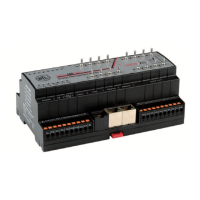
OPEN 600 EMS
Technische Daten
Gehäuse:
• Abmessungen (BxTxH): 160 mm x 60 mm x 90 (98) mm
• Material: Kunststoff
• Montage: auf Standard-Hutschiene 35 mm
• Schutzart: IP 20
• Kühlung: lüfterlos durch Konvektion
• Temperaturbereich: 0..50 °C
• Anschluss: abziehbare Federzugklemmen
Nennquerschnitt 1,5 mm²
• Anzeige LEDs Betriebsanzeige,
Error,
Run,
CAN-Bus
COM-Schnittstelle
Ethernet
• Einbaulage: beliebig
Spannungsversorgung:
• Eingangsspannung: U(nenn) = 24 V DC (19 .. 30 V DC)
• Eingangsstrom: I(nenn) = ca. 200 mA
• Leistungsaufnahme: ca. 5 W
• max. Vorsicherung: 2 A
Mikroprozessor und Speicher:
• CPU: PowerPC, 220 MHz
• RAM-Speicher: 128 MB
• NV-RAM Batterie-gepuffert: 2 MB
• Flash-Speicher: 2 GB Micro SD Karte
• Uhr: batteriegepufferte Echtzeituhr
• Watchdog: Hardware-Watchdog
Schnittstellen:
• Fast Ethernet: 2 x 10/100 BaseT (RJ45)
jeweils mit LED Anzeige
• RS232 1 x RS232, Anschluss über RJ45
mit LED Anzeige
• RS485 1x RS485, galvanisch entkoppelt,
mit LED Anzeige
Anschluss: abziehbare Federzug
klemmen, Nennquerschnitt 1,5 mm²
Kommunikation:
• CAN-Bus CAN 2.0B,
galvanisch getrennt ISO 11898
• Übertragungsrate 10 kbit/s... 1Mbit/s,
voreingestellt 50 kbit/s
• Anschluss: über Brückenbusstecker
• Busleitung: CAN-Bus Leitung,
Wellenwiderstand R
W
= 120 Ohm
• Busabschlusswiderstand: R
W
am Anfang und am Ende
des Busses
Technical data
Housing:
• Dimensions (WxDxH): 160 mm x 60 mm x 90 (98) mm
• Material: Plastic
• Mounting: on Standard mounting rail 35 mm
• Protection class: IP 20
• Cooling: no fan ; by convection
• Temperature range: 0..50 °C
• Connection: removable spring terminals
Nominal wire 1,5 mm²
• Display LEDs: operating display,
Error,
Run,
CAN-bus
COM interface
Ethernet
• Mounting position: optional
Power supply:
• Input voltage: U(typ.) = 24 V DC (19 .. 30 V DC)
• Input current: I(typ.) = approx. 200 mA
• Power consumption: approx. 5 W
• max. back-up fuse: 2 A
Microprocessor and memory:
• CPU: PowerPC, 220 MHz
• RAM memory: 128 MB
• NV-RAM battery buffered: 2 MB
• Flash memory: 2 GB Micro SD card
• Clock: battery buffered real time clock
• Watchdog: Hardware-Watchdog
Interface:
• Fast Ethernet: 2 x 10/100 BaseT (RJ45)
each with LED display
• RS232: 1 x RS232, connection via RJ45
with LED display
• RS485: 1x RS485, galvanically decoupled,
with LED display
Connection: removable spring
terminals, Nominal wire 1,5 mm²
Communication:
• CAN-bus: CAN 2.0B,
galvanically isolated ISO 11898
• Transmission rate: 10 kbit/s...1Mbit/s,
default 50 kbit/s
• Connection: via bridge bus connector
• Bus line: CAN-bus line
wave resistance R
W
= 120 Ohm
• Terminating resistor: R
W
at the beginning and at the end
of the bus
 Loading...