Do you have a question about the Det-Tronics SmokeWatch U5015 and is the answer not in the manual?
Initial power-up sequence involving internal checks and communication, indicated by LED status.
Details the detector's 0-20 mA current output, LED status, and relay functionalities (alarm, fault, auxiliary).
Describes the integrated junction box for external wiring connections.
Explains the function of the LED for indicating detector status (e.g., normal, alarm).
Defines alarm behavior configurations: indefinite alarm state (latching) or self-clearing (non-latching).
Details continuous background self-testing and manual self-test initiation via magnetic switch.
Recommendations for using thread lubricant on covers and fittings for ease of installation and removal.
Guidance on determining optimal detector placement based on site conditions and accessibility.
Precautions for preventing moisture ingress into electrical connections during installation.
Guidance on calculating and selecting an adequate power supply for the detection system.
Instructions on the purpose and removal timing of the transport cover.
Details on ceiling and wall mounting orientations and considerations for LED visibility.
Instructions for physically securing the detector unit to the mounting surface.
Specifications for cable types, gauge, shielding, and termination for safe and reliable wiring.
Guidance on using jumpers for different wiring options (0-20 mA, Relay) as per usage guide.
Step-by-step instructions for connecting external wiring to the detector terminals.
Recommendations for periodic visual inspection of the cover and smoke chamber for blockages.
List of available spare parts for the U5015 detector, including the replacement sensor module.
Catalog of optional accessories such as tester, grease, magnet, and mounting options.
Table detailing model configurations for material, ports, thread type, outputs, and approvals.
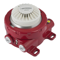
The Det-Tronics SmokeWatch™ U5015 Explosion Proof Smoke Detector is designed for industrial and commercial applications, offering reliable smoke detection in hazardous environments. It is engineered to effectively detect both smoldering and rapidly growing fires, providing robust protection and ensuring no undisclosed failures through its self-checking circuitry.
The U5015 detector utilizes photoelectric operation to detect smoke. It provides multiple output signals to communicate its status to other devices and control systems. These outputs include a 0-20 mA current signal for integration with Distributed Control Systems (DCS) or Programmable Logic Controllers (PLC), a localized LED for visual indication, and three types of relays: a smoke alarm relay, a fault relay, and an auxiliary relay. The smoke alarm relay is normally open/normally closed with de-energized operation, while the fault relay has normally open contacts with energized operation. The auxiliary relay, which functions as a pre-alarm, also has normally open/normally closed contacts with de-energized operation. This comprehensive set of outputs allows for flexible integration into various fire safety and control systems.
The device incorporates continuous self-test capabilities, performing checks in the background once per second without interrupting detection. If a test fails, a critical fault occurs, and if degradation is present and approaching critical levels, an advisory fault is annunciated. A manual self-test function can also be initiated using a magnetic switch, which immediately checks the smoke chamber optics for degradation.
The U5015 is FM Approved for use in Class I, Division 1 hazardous locations and for smoke detection performance, and is IECEx Zone approved. Its IP44 ingress protection level makes it suitable for both onshore and offshore requirements. The detector's rugged design is built to withstand environmental extremes, making it ideal for classified areas in industries such as petrochemical, oil, and gas.
The hot-swappable sensor module is intrinsically safe, allowing for live maintenance without de-classifying the hazardous area. This feature simplifies upkeep and reduces downtime. The integrated junction box offers various port configurations for simplified wiring and installation, enhancing ease of deployment.
The detector supports both latching and non-latching operations, which must be specified during order placement as they are not field configurable. In latching mode, the detector remains in an alarm state indefinitely until power is cycled. In non-latching mode, the detector checks its alarm status every 10 seconds, clearing the alarm annunciation within 10 seconds once smoke levels fall below the threshold. The LED provides clear visual indications: steady off for power on/normal operation, one blink every four seconds for normal operation, and steady on for an alarm.
Mounting options include ceiling mount and wall mount. For ceiling mounting, the detector should be no less than six inches from a side wall. For wall mounting, the exact location should be determined by engineering judgment or field tests. In both cases, it is important to select an orientation where the LED is visible to personnel.
Proper installation is crucial for the U5015. All entries must have appropriately rated plugs or fittings, wrench-tightened to the specified torque, and meet minimum thread engagement requirements. PTFE sealant or equivalent should be used on NPT threads for enhanced sealing. The detector housings must be electrically connected to earth ground, with internal and external terminals provided for this purpose. Thread lubricant is recommended for all threaded covers, stopping plugs, and adapters to ease installation and future removal.
Wiring requires proper temperature-rated cabling (14 to 18 AWG shielded stranded copper wire is recommended). Cable insulation should be stripped to a maximum bare conductor length of 0.28 inches (7 mm), ensuring the shield is properly terminated and does not contact the metal housing or other wires. Jumpers may be required depending on the chosen wiring option.
The U5015 Smoke Detector is designed with minimal user-serviceable components. The sensor module is field replaceable in case of damage or failure. However, the detector itself is not field repairable and should be returned to the factory for repair if found faulty. The wiring compartment is the only part of the smoke detector that should be opened by the user in the field.
Regularly scheduled maintenance is not typically required, but periodic inspection of the cover and smoke chamber is recommended, especially in dirty or dusty environments, to ensure the chamber is not blocked by debris. To test the smoke detector, a test aerosol smoke dispenser can be used, similar to methods employed for other photo-electric detectors.
When handling the U5015 sensor module, precautions for electrostatic sensitive devices should be observed, and the surface should not be wiped or rubbed to avoid potential electrostatic discharge (ESD). The transport cover should remain fastened during transport, handling, and installation, and only removed prior to powering the detector for the first time.
| Operating Temperature | -40°F to 158°F (-40°C to 70°C) |
|---|---|
| Humidity | 0% to 95% RH (non-condensing) |
| Power Supply | 24 VDC (18-32 VDC) |
| Approvals | FM |
| Material | Stainless steel |
| Operating Voltage | 18-30 VDC |
| Humidity Range | 0% to 95% RH (non-condensing) |
| Housing Material | Stainless steel |
| Certifications | FM |