This alarm should be installed as late as possible within the schedule of
works, particularly in new build properties, e.g. after decorating and
making good works.
• This alarm must not be connected to any other manufacturer alarms.
• The combined Smoke and Heat alarm is compatible with DETA item
numbers, 1163, 1165, 1164 and 1166 and 1169; and can be
hardwired interlinked with these alarms. It is not compatible with the
previous generations.
Important
The circuit powering the safety alarms must be unswitched, i.e.
permanently live. The electrical supply for mains powered alarms with
battery back-up, as required by BS 5839-6 Grade D systems, must:
i) Be an independent circuit from the consumer unit where no other
electrical equipment is connected, or
ii) A separately electrically protected, regularly used local lighting circuit
Also, where alarms are interlinked, they must be connected to a single
circuit.
Safety Instructions
• Ensure the power supply is switched off before installation and
during maintenance.
• These alarms should be installed by a competent person, e.g. a
qualified electrician.
• These alarms must be installed in accordance with the current
edition of the IET Wiring Regulations BS7671 and the Code of Practice
for the design, installation, commissioning and maintenance of fire
detection and fire alarm systems in domestic premises BS
5839-6.
• Important: Remove the alarm from the circuit for insulation
resistance testing.
If in doubt, contact a qualified electrician.
Installation
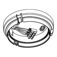
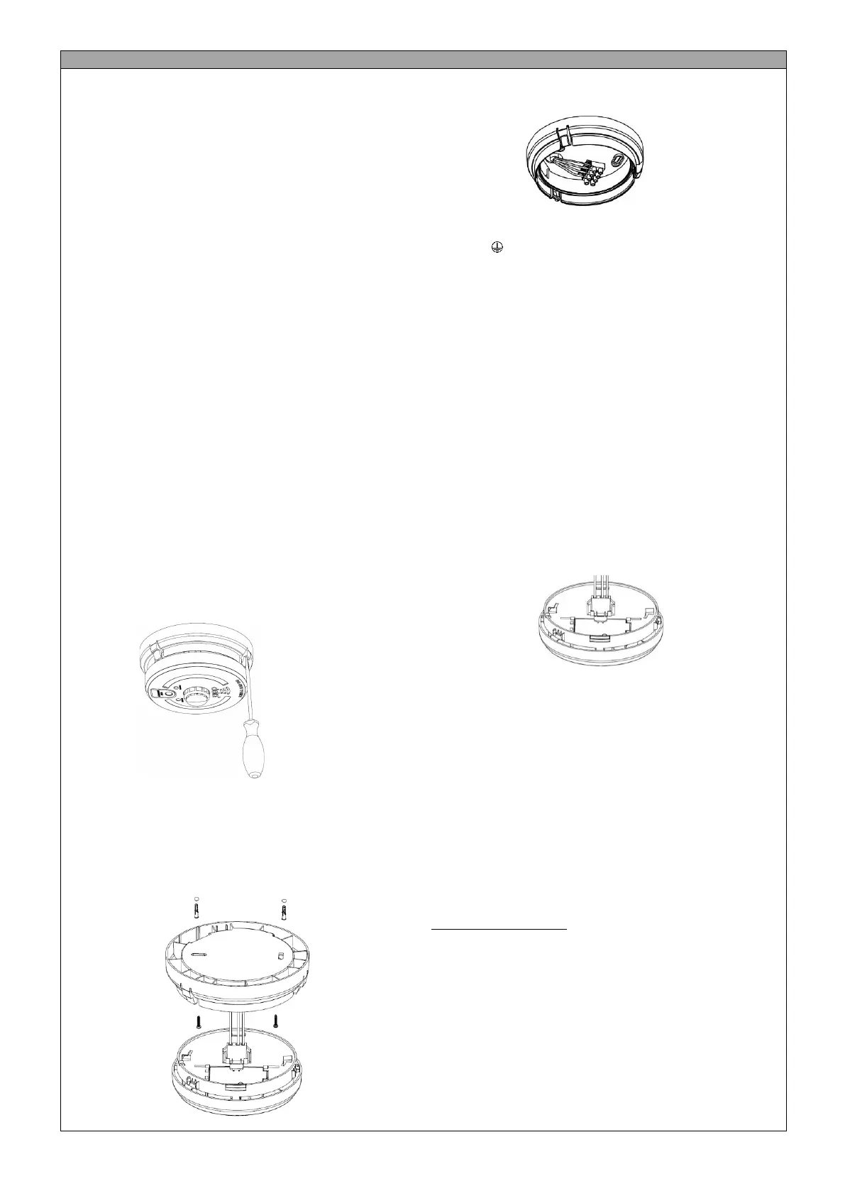
1. Release the alarm from the base by using a screw insert into the slots
and flexing outwards, see diagram. 4
Diagram 4
2. Remove the electrical connector from the alarm by squeezing the
locking arms.
3. Select the cable entry on the base and remove the cut out. Cable
entry can either be through the back of the base or via surface
mounted mini-trunking. Leave the gasket in place to prevent dust
ingress into the alarm.
4. Mount the base in the desired location using the wall plugs and screws,
as required. See Diagram 5.
Diagram 5
5. Terminate the live, neutral and earth supply cables and interlink cable
if alarms are interlinked. See Diagram 6.
Diagram 6.
L (Live): Brown conductor
N (Neutral): Blue conductor
E (Earth): Green / Yellow
I (Interlink): Grey (if using 6243Y cable)
6. Interlink
• A maximum of 12 alarms can be hardwired interlinked in a
system. If more than 12 alarms are interlinked it may result in
permanent damage.
• A maximum of 50 Combined alarms (1171 only) can be
wirelessly interlinked (see Wireless Interconnection section)
• 1171 can also be installed in a hybrid system containing
hardwired and wirelessly interlinked alarms. In a hybrid system
containing hardwired and wireless interlink connections, it is
recommended that each group of hardwired alarms is
hardwired to only one wireless alarm, which interlinks
wirelessly with other wireless products.
7. For multiple alarm installations use three core and earth cable
between all the alarms to be interlinked and connect the third core of
that cable to terminal marked I. DO NOT use the earth wire for the
interlink wire. This must be treated as live, i.e. insulated and sleeved.
8. Connect the battery:
• On 1171 by pulling tab on the sealed battery cover.
• Test the alarm by pressing the TEST button.
9. Refit the electrical connector, see Diagram 7.
Diagram 7
10. Attached the alarm to the base
11. Turn on the electrical power. The green LED should be lit when the
alarm is operating from the power supply.
12. Test the alarm, including the interlink feature if more than one alarm is
installed.
Important: Remove the alarm from the circuit for insulation
resistance testing.
Wireless Interlink Instructions
Combined Optical and Heat alarm is fitted with an RF module which allows
up to 50 alarms to be wirelessly interlinked in a system. A hybrid system
can have up to 12 hardwired and 50 wirelessly interlinked alarms. For a
quick set-up of the alarm system network, it is recommended that the all
alarms are placed in close proximity to each other on a flat surface.
Setting up a wireless network
1. To setup up a wireless network, take one alarm and press the alarm
test button 3 times within 2 seconds. The RED LED on the alarm will
light up indicating that the alarm has entered the networking mode
and is ready to be paired with other alarms. The next alarm must be
added to the system within 30 seconds or the network will timeout.
2. To add another alarm to the network, press the alarm test button 3
times within 2 seconds. The secondary alarm should automatically
pair with the first; and a successful pairing is confirmed by a single
LED flash and a beep. Each time a new alarm is added, the
networking time period is extended by 30 seconds for adding more
alarms to the system.
3. Once all the alarms are added to the network, wait for 30 seconds to
allow the network to time out. To test the interlink, press and hold
the test button on any alarm in the network (see Testing the Alarm).
 Loading...