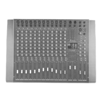
This document is the owner's manual for the DETON MD Series Professional Mixers, including models MD82, MD82A, MD122, and MD122A. These mixers are designed for professional sound system applications, offering convenient operation and a range of functions suitable for various demands.
General Description
The MD Series mixers are newly developed devices that excel in function and ease of use. They feature high-gain and low-noise microphone inputs, a digital signal processor (DSP), and 100mm slip potentiometers, making them versatile for a wide array of audio mixing tasks.
Channel Section
Each channel of the mixer shares common control functions, ensuring a consistent user experience across all inputs.
- Function: Electronically accepts standard XLR male connectors.
- Wiring: Pin 1 is Ground (shield), Pin 2 is HOT (signal input), and Pin 3 is COLD (ground/shield).
- Usage: The GAIN control allows adjustment of input sensitivity from a maximum of 20dB to 60dB, depending on the signal level.
- Function: Utilizes 1/4" standard line connectors.
- Wiring: Supports both unbalanced (tip/sleeve) and balanced (tip/ring/sleeve) connections. Tip is positive, ring is negative, and sleeve is ground.
- Usage: Can be connected to keyboards and other electronic instruments.
PAD (-20dB)
- Function: Attenuates the input signal by 20dB.
- Usage: Press this switch to reduce the input signal level when necessary, preventing overload.
CLIP (Peak Level Indicator)
- Function: An LED indicator that illuminates when the post-EQ, per-fader signal of that channel is within 10dB of actual clipping.
- Usage: Serves as a visual warning to prevent signal distortion.
GAIN Control
- Function: Adjusts the input sensitivity of the channel.
- Usage: With the -20dB pad switch in the out position, sensitivity can be adjusted from -60dB to -20dB. When the -20dB pad switch is pushed, the range is -40dB to 0dB.
High Frequency Equalization Control
- Function: Provides ±15dB of fixed frequency equalization that shelves at 12KHz.
- Usage: Allows for adjustment of the high-frequency content of the channel's signal.
Mid Frequency Equalization Control
- Function: Provides ±15dB of fixed frequency equalization that shelves between 250KHz and 6KHz.
- Usage: Enables adjustment of the mid-range frequency content.
Lo Frequency Equalization Control
- Function: Provides ±15dB of fixed frequency equalization that shelves at 100Hz.
- Usage: Allows for adjustment of the low-frequency content.
Effect Control
- Function: Adjusts the input signal level to achieve desired effect sound.
- Usage: When no external source is used, the internal digital delay will be active.
AUX Control
- Function: Sets the level of the signal sent to an external stereo source.
- Usage: The main signal control for AUX is managed by the master section.
PAN Control
- Function: Continuously varies the amount of post-fader signal sent to the Left and Right main busses.
- Usage: In the center position, equal amounts of signal are sent to both busses. Rotating the control in either direction sends more signal to the indicated buss and less to the other. When turned all the way to one side, the signal is sent only to that side.
Channel ON/OFF
- Function: Activates or deactivates the channel.
- Usage: Pressing this button illuminates a green LED, indicating the channel is active. Turning off unused channels can improve the signal-to-noise ratio and reduce unnecessary noise, enhancing the overall sound quality.
Pre-Fader Level (PFL)
- Function: Allows monitoring of the signal of a specific channel before the fader.
- Usage: When the PFL switch is turned on, other channels are automatically muted for headphone monitoring. Refer to the monitor section for more details.
Indication
- Function: Provides an easy way to identify the input signal.
- Usage: Input signals can be easily identified by referring to the sticker.
Channel Fader
- Function: Adjusts the volume of signal sources connected to the respective channel.
- Usage: Move the fader up or down to control the output level of the channel.
Master Section
The master section provides overall control and monitoring for the mixer's output.
Left & Right Master Busses Balanced Output Jack
- Function: Provides balanced stereo output.
- Wiring: Pin 3 is COLD, Pin 2 is HOT, and Pin 1 is GROUND (shield).
Left & Right Master Busses Unbalance Jack
- Function: Provides unbalanced stereo output.
- Wiring: Tip is signal (+), ring is ground (-), and sleeve is GROUND (shield).
Master Level Display
- Function: A VU-meter that shows the output levels of the left and right channels and the overall working condition.
- Usage: Allows users to monitor output levels and ensure they do not exceed +3dB to prevent distortion. The lamp indicates whether the power is on or off.
Stereo Graphic Equalizer (Left and Right)
- Function: Differentiates and adjusts the frequency of the signal.
- Usage: Each channel band can be adjusted to suit listening position and listener's taste. Moving the control upwards increases the level, and vice versa.
Left Master Fader
- Function: Adjusts the final mixed left output.
- Usage: Move the fader to control the overall volume of the left channel.
Right Master Fader
- Function: Adjusts the final mixed right output.
- Usage: Move the fader to control the overall volume of the right channel.
DSP Digital Indicator
- Function: Indicates the currently active effect from the Digital Signal Processor (DSP).
DSP Presets (Up and Down)
- Function: Allows selection of different DSP presets.
- Usage: Pressing the up or down buttons changes the preset number. When a preset is selected, the LED illuminates, but the effect output is only active after pressing the ENTER key. The LED will stop flashing once the effect is active.
- Function: Indicates the DSP signal input level.
- Usage: If the red LED illuminates, the input level should be reduced slightly to prevent clipping.
Internal DSP
- Function: Offers 32 different effects.
- Usage: Users can choose from a variety of effects to enhance their audio.
DSP Enter
- Function: Activates the selected DSP preset.
- Usage: After choosing a preset, press this key to engage the DSP effect.
AUX Section
The AUX section provides controls for auxiliary inputs, outputs, and monitoring.
- Function: A 1/4" stereo jack for connecting stereo effect equipment or other external auxiliary signals.
- Wiring: Tip is left signal, ring is right signal, and sleeve is negative.
AUX Output
- Function: Connects to the input jack of a monitor amplifier when using a separate monitor amplifier.
Stereo Recorder & Phono Jack (Play In / Rec Out)
- Function:
- Play In: Connects to a cassette deck for playing back recorded audio.
- Rec Out: Connects to a cassette deck for recording the mixed output.
Headphone Jack
- Function: Allows monitoring of the working condition of the mixer through headphones.
- Usage: Can monitor the master sound and individual channels.
Pre-Fader Level (PFL) Control
- Function: Monitors a specific channel before the fader.
- Usage: Push this switch to turn on the LED and monitor a single channel. Release the switch to monitor the master output.
Headphone Volume Control
- Function: Adjusts the output level of the headphones.
- Function: Controls the input level from the AUX INPUT.
- Usage: Adjust to control the volume of playback from AUX INPUT (see No.1).
Monitor Hi Frequency Equalization Control
- Function: Equalizes the 12KHz frequency from AUX INPUT.
- Usage: Provides ±15dB of level adjustment for high frequencies.
Monitor Lo Frequency Equalization Control
- Function: Equalizes the 100KHz frequency from AUX INPUT.
- Usage: Provides ±15dB of level adjustment for low frequencies.
AUX Effect Control
- Function: Adjusts the effect level of the AUX INPUT.
Channel Switch
- Function: Connects the auxiliary input.
- Usage: Press the button to connect the auxiliary input for better voice quality; release it if not needed.
PFL Switch Control
- Function: Monitors the AUX INPUT signals.
- Usage: Adjust this button to monitor the auxiliary input signals.
Master Monitor Control
- Function: Adjusts the final output level from the AUX section.
Effect Section
The effect section manages external and internal effects processing.
Left and Right AUX Effect Return
- Function: Connects to other external processors.
- Function: Used with a movable microphone for the DJ.
- Wiring: Pin 1 is GROUND (shield), Pin 2 is HOT (signal input), and Pin 3 is COLD (ground/shield).
Talkback Level Control
- Function: Sets the level of the talkback input.
- Usage: Adjust the knob to control the volume of the talkback microphone.
Talkback Signal Distribution Control
- Function: Distributes the talkback signal to various channels.
- Usage:
- AUX: Push to distribute the signal to the Auxiliary channel.
- EFF: Push to distribute the signal to the Effect channel.
- L/R: Push to distribute the signal to the L/R channel.
Phantom Power Switch (+48V)
- Function: Provides +48V phantom power for microphones that require it.
- Usage: Push the button through the small hole to switch on. The LED will illuminate when active.
Left Master Level Control
- Function: Controls the AUX return level for the left channel.
- Usage: Adjust the knob to set the desired level.
Right Master Level Control
- Function: Controls the AUX return level for the right channel.
- Usage: Adjust the knob to set the desired level.
- Function: Controls the level of the signal being sent to the digital DST.
- Usage: Adjust this control to manage the input level for digital effects.
PAN Control
- Function: Adjusts the echo sound and external effector sound between left and right channels.
Channel Switch Control
- Function: Engages or disengages the effect for the main channel.
- Usage: Push the button to send the effect to the main channel. Release it for a cleaner voice without effects.
PFL Switch
- Function: Monitors the effect independently via headphones.
- Usage: Push this button to solo the effect for monitoring.
Effect Fader Control
- Function: Adjusts the signal level of the external effector.
- Usage: Use this fader to control the overall volume of the effects.
Maintenance Features
Safety Warnings
- Electric Shock Risk: Do not open the mixer's cover or back. There are no user-serviceable parts inside. Refer all servicing to qualified service personnel.
- Moisture Exposure: To reduce the risk of electric shock, do not expose the equipment to rain or moisture.
Magnetic Field Caution
- Placement: Do not locate sensitive high-gain equipment (e.g., preamplifiers, tape decks) directly above or below the mixer. The mixer has a high power density and generates a strong magnetic field that can induce hum in unshielded devices nearby. The field is strongest just above and below the unit.
- Rack Mounting: If using an equipment rack, it is recommended to locate the amplifiers at the bottom of the rack and sensitive equipment (like preamplifiers) at the top to minimize interference.
Symbol Interpretation
- Lightning Bolt Triangle: Alerts the user to the risk of electric shock.
- Exclamation Point Triangle: Alerts the user to important operating or maintenance instructions.