ENGLISH
8
b. Check to see if receptacle is connected to a light
switch which turns power off when you turn out
the lights;
c. Move the charger and battery pack to a location
where the surrounding air temperature is
approximately 65°F – 75°F (18° – 24°C);
d. If charging problems persist, take the tool, battery
pack and charger to your local service center.
4. The battery pack should be recharged when it fails to
produce sufficient power on jobs which were easily
done previously. DO NOT CONTINUE to use under these
conditions. Follow the charging procedure. You may
also charge a partially used pack whenever you desire
with no adverse effect on the battery pack.
5. Foreign materials of a conductive nature such as, but
not limited to, grinding dust, metal chips, steel wool,
aluminum foil, or any buildup of metallic particles
should be kept away from charger cavities. Always
unplug the charger from the power supply when there
is no battery pack in the cavity. Unplug the charger
before attempting to clean.
6. Do not freeze or immerse the charger in water or any
other liquid.
Storage Recommendations
1. The best storage place is one that is cool and dry, away
from direct sunlight and excess heat or cold.
2. For long storage, it is recommended to store a fully
charged battery pack in a cool dry place out of the
charger for optimal results.
NOTE: Battery packs should not be stored completely
depleted of charge. The battery pack will need to be
recharged before use.
SAVE THESE INSTRUCTIONS FOR
FUTURE USE
Intended Use
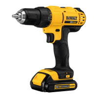
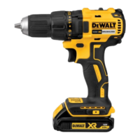
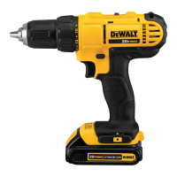
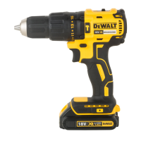
These drills/drivers/hammerdrills are designed
for professional drilling, screwdriving and
hammerdrillingapplications.
DO NOT use under wet conditions or in presence of
flammable liquids orgases.
These drills/drivers/hammerdrills are professional power
tools. DO NOT let children come into contact with the tool.
Supervision is required when inexperienced operators use
thistool.
ASSEMBLY AND ADJUSTMENTS
WARNING: To reduce the risk of serious personal
injury, turn unit off and remove the battery pack
before making any adjustments or removing/
installing attachments or accessories. An
accidental start-up can causeinjury.
Installing a Bit or Accessory into a
Keyless Chuck (Fig. D)
WARNING: Do not attempt to tighten drill bits (or
any other accessory) by gripping the front part of the
chuck and turning the tool on. Damage to the chuck
and personal injury may result. Always lock off trigger
switch and disconnect tool from power source when
changingacces sories.
WARNING: Always ensure the bit is secure before
starting the tool. A loose bit may eject from tool
causing possible personalinjury.
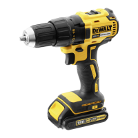
Your tool features a keyless chuck
6
with one rotating
sleeve for one-handed operation of the chuck. To insert a
drill bit or other accessory, follow thesesteps.
1. Turn tool off and remove battery pack.
2. Grasp the black sleeve of the chuck with one hand
and use the other hand to secure the tool. Rotate the
sleeve counterclockwise far enough to accept the
desiredaccessory.
3. Insert the accessory about 3/4" (19 mm) into the chuck
and tighten securely by rotating the chuck sleeve
clockwise with one hand while holding the tool with the
other. Your tool is equipped with an automatic spindle
lock mechanism. This allows you to open and close the
chuck with onehand.
Be sure to tighten chuck with one hand on the chuck sleeve
and one hand holding the tool for maximumtightness.
To release the accessory, repeat steps 1 and 2above.
Fig.D
6
Speed Selection (Fig. A)
The tool features two speed settings for greaterversatility.
NOTE: Do not change speeds when the tool is running.
Always allow the tool to come to a complete stop before
changingspeed.
1. To select speed 1 (higher torque setting), slide the
speed selector
4
back (away from the chuck).
2. To select speed 2 (lower torque setting), slide the speed
selector forward (towards the chuck).
If the tool does not change speeds, confirm that the speed
selection switch is completely engaged in the forward or
back position.
Mode Selection (Fig. A)
The mode selection collar
3
can be used to select
the correct operating mode depending upon the
plannedapplication.
 Loading...
