ENGLISH
7
Cleaning
WARNING: Blo
w dirt and dust out of all air vents with
clean, dry air at least once a week. To minimize the risk of eye
injury, always wear ANSI Z87.1 approved eye protection when
perform
ing thisprocedure.
WARNING:
Never use solvents or other harsh chemicals
for cleaning the non‑metallic parts of the tool. These chemicals
may weaken the plastic materials used in these parts. Use a
cloth dampened only with water and mild soap. Never let any
liquid get inside the tool; never immerse any part of the tool
into aliquid.
MAINTENANCE
WARNING: To reduce the risk of serious personal
injury, turn unit off and remove the battery pack
before making any adjustments or removing/installing
attachments or accessories. An accidental start‑up can
causeinjury.
Your DeWALT power tool has been designed to operate
over a long period of time with a minimum of maintenance.
Continuous satisfactory operation depends upon proper
tool care and regularcleaning.
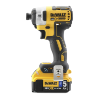
Specifications
Max. fastening torque
Precision Wrench™ mode: 600 ft-lbs, 812 Nm
Low Mode: 100 ft-lbs, 136 Nm
Medium mode: 300 ft-lbs, 406 Nm
High mode: 600 ft-lbs, 812 Nm
Max. breakaway torque 800 ft-lbs, 1084 Nm
No load speed 0–2000 rpm
Impacts per minute 0–3250 ipm
Length 6.95" (177 mm)
Weight 3.7 lbs (1.67 kg)
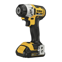
Usage (Fig.A)
CAUTION: Ensure fastener and/or system will withstand
the level of torque generated by the tool. Excessive torque may
cause breakage and possible personalinjury.
1. Place the accessory on the fastener head. Keep the tool
pointed straight at thefastener.
2. Press variable speed trigger switch
1
to start operation.
Release variable speed trigger switch to stop operation.
Always check torque with a torque wrench, as the fastening
torque is affected by many factors including the following:
‑ Voltage: Low voltage, due to a nearly discharged battery,
will reduce fasteningtorque.
Worklight (Fig.A, B)
The worklight
7
is activated when the variable
speed trigger
1
is depressed. Pressing the worklight
switch
8
repeatedly will cycle through low illumination,
high illumination, andoff.
NOTE: The worklight is for lighting the immediate work
surface and is not intended to be used as aflashlight.
Forward/Reverse Control Button (Fig.A)
A forward/reverse control button
2
determines the
direction of the tool and also serves as a lock-offbutton.
To select forward rotation, release the trigger switch and
depress the forward/reverse control button on the right side
of thetool.
To select reverse, release the trigger switch and depress the
forward/reverse control button on the left side of thetool.
The center position of the control button locks the tool in
the off position. When changing the position of the control
button, be sure the trigger isreleased.
NOTE: The first time the tool is run after changing the
direction of rotation, you may hear a click on start-up. This is
normal and does not indicate aproblem.
‑ Accessory size: Failure to use the correct accessory size
will cause a reduction in fasteningtorque.
‑ Bolt size: Larger bolt diameters generally require higher
fastening torque. Fastening torque will also vary according
to length, grade, and torquecoefficient.
‑ Bolt: Ensure that all threads are free of rust and other
debris to allow proper fasteningtorque.
‑ Material: The type of material and surface finish of the
material will affect fasteningtorque.
‑ Fastening time: Longer fasten ing time results in
increased fastening torque. Using a longer fastening
time than recommended could cause the fasteners to be
overstressed, stripped ordamaged.
Variable Speed Trigger Switch (Fig.A)
To turn the tool on, squeeze the trigger switch
1
. To turn
the tool off, release the trigger switch. Your tool is equipped
with a brake. The anvil will stop when the trigger switch
is fully released. The variable speed switch enables you to
select the best speed for a particular application. The more
you squeeze the trigger, the faster the tool will operate. For
maximum tool life, use variable speed only for starting holes
orfasteners.
NOTE: Continuous use in variable speed range is not
recommended. It may damage the switch and should
beavoided.
Proper Hand Position (Fig.E)
WARNING: To reduce the risk of serious personal injury,
ALWAYS use proper hand position as shown.
WARNING: To reduce the risk of serious personal injury,
ALWAYS hold securely in anticipation of a suddenreaction.
Proper hand position requires one hand on the main
handle
4
.
it into the handle until the battery pack is firmly seated in
the tool and ensure that it does notdisengage.
To remove the battery pack from the tool, press the release
button
5
and firmly pull the battery pack out of the tool
handle. Insert it into the charger.
Accessories
WARNING: Since accessories, other than those offered by
DeWALT, have not been tested with this product, use of such
accessories with this product could be hazardous. To reduce
the risk of injury, only DeWALT recommended accessories
should be used with thisproduct.
Recommended accessories for use with your product are
available at extra cost from your local dealer or authorized
service center. If you need assistance in locating any
accessory, please contact DeWALT. Call 1-800-4-DeWALT
(1-800-433-9258) or visit our website: www.dewalt.com.
 Loading...