43
ENGLISH
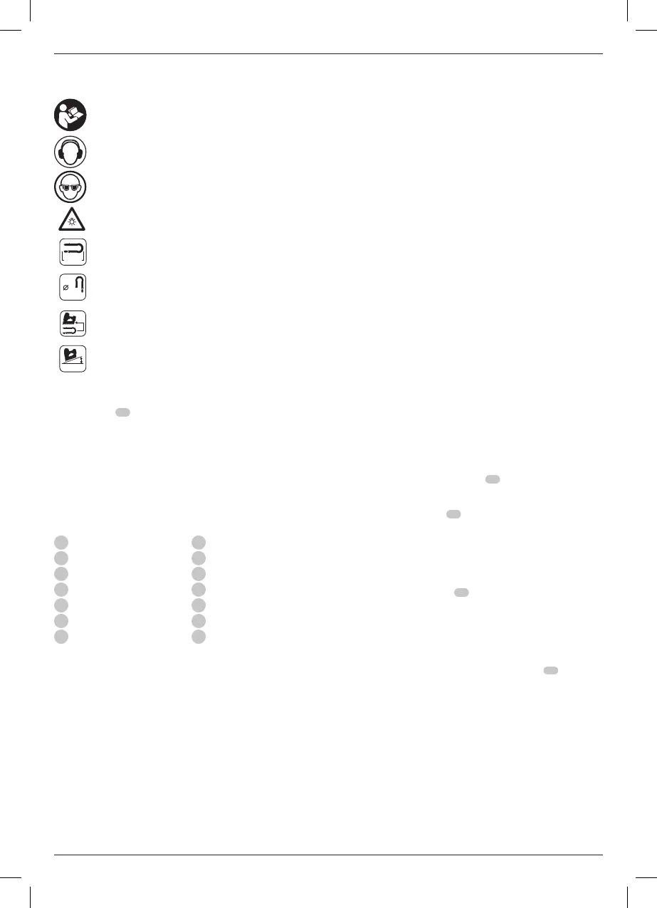
Markings on Tool
The following pictograms are shown on the tool:
Read instruction manual beforeuse.
Wear earprotection.
Wear eyeprotection.
Visible radiation. Do not stare intolight.
40-50mm
Length ofstaples.
9GA
3.7-4.0mm
Staplethickness.
38
Loadingcapacity.
0°
Suitable staple collationangle.
Date Code Position (Fig. A)
The date code
17
, which also includes the year of manufacture,
is printed into thehousing.
Example:
2019 XX XX
Year of Manufacture
Description (Fig. A)
WARNING: Never modify the power tool or any part of it.
Damage or personal injury couldresult.
1
Trigger
2
Trigger lock-off
3
Tool free speed select
4
Tool free mode select
5
Utility hook
6
Tool free depth adjust
7
Contact trip
8
Tool free stall release
9
LED work lights (x2)
10
Magazine
11
Magazine release
12
Pusher
13
Battery release button
14
Battery
Intended Use
Your fencing stapler is intended ONLY for use in driving staples
into wood. This tool has two operating modes, a sequential
operating mode and a unique rapid sequential operating mode
(RapidCycle). Read the section of the manual Selecting the
Mode before using the tool to make sure you are selecting the
proper mode for yourapplication.
DO NOT use under wet conditions or in the presence of
flammable liquids orgases.
Your fencing stapler is a professional powertool.
Only
staples meeting applicable building code
requirements should be used in thistool.
This tool is intended for use by constructionprofessionals.
DO NOT let children come into contact with the tool.
Supervision is required when inexperienced operators use
thistool.
• Young children and the infirm. This appliance is not
intended for use by young children or infirm persons
withoutsupervision.
• This product is not intended for use by persons (including
children) suffering from diminished physical, sensory or
mental abilities; lack of experience, knowledge or skills
unless they are supervised by a person responsible for their
safety. Children should never be left alone with thisproduct.
Dry Fire Lock Out
Your stapler is equipped with a dry fire lockout which prevents
the tool from actuating when the magazine is nearly empty.
When 5 staples remain in the magazine, the tool ceases
to operate. Refer to LoadingtheTool to reload a stick of
collatedstaples.
ASSEMBLY AND ADJUSTMENTS
WARNING: To reduce the risk of serious personal
injury, turn tool off and disconnect battery pack
before making any adjustments or removing/
installing attachments or accessories. An accidental
start-up can causeinjury.
WARNING: Use only
battery packs andchargers.
Inserting and Removing the Battery Pack
from the Tool (Fig. B)
NOTE: Make sure your battery pack
14
is fullycharged.
To Install the Battery Pack into the Tool Handle
1. Align the battery pack
14
with the rails inside the tool’s
handle (Fig.B).
2. Slide it into the handle until the battery pack is firmly seated
in the tool and ensure that you hear the lock snap intoplace.
To Remove the Battery Pack from the Tool
1. Press the release button
13
and firmly pull the battery pack
out of the toolhandle.
2. Insert battery pack into the charger as described in the
charger section of thismanual.
Fuel Gauge Battery Packs (Fig. B)
Some
battery packs include a fuel gauge
23
which
consists of three green LED lights that indicate the level of
charge remaining in the batterypack.
To actuate the fuel gauge, press and hold the fuel gauge button.
A combination of the three green LED lights will illuminate
designating the level of charge left. When the level of charge
in the battery is below the usable limit, the fuel gauge will not
illuminate and the battery will need to berecharged.
NOTE: The fuel gauge is only an indication of the charge left on
the battery pack. It does not indicate tool functionality and is
subject to variation based on product components, temperature
and end-userapplication.
 Loading...