48
ENGLISH
Always mount your saw firmly to a stable surface to prevent movement.
To enhance the tool’s portability, it can be mounted to a piece of 12.7 mm
or thicker plywood which can then be clamped to your work support or
moved to other job sites andreclamped.
NOTE: If you elect to mount your saw to a piece of plywood, make sure that
the mounting screws don’t protrude from the bottom of the wood. The
plywood must sit flush on the work support. When clamping the saw to
any work surface, clamp only on the clamping bosses where the mounting
screw holes are located. Clamping at any other point will interfere with the
proper operation of thesaw.
CAUTION: To prevent binding and inaccuracy, be sure the mounting
surface is not warped or otherwise uneven. If the saw rocks on the
surface, place a thin piece of material under one saw foot until the saw
sits firmly on the mountingsurface.
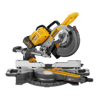
Assembling the Base Extensions (Fig. Z)
WARNING: Base extensions must be assembled to both sides of
the saw's base before using thesaw.
WARNING: Be sure to adjust the base extensions using the
mounting holes so they are level with the saw'sbase.
1. Locate the holes above the hand indentations
16
on the side of
thebase.
2. Using the supplied wrench or a T30 wrench, attach the screw
63
through the washer
64
, through the base extension
15
, and into the
holes on thebase.
3. Ensure the extension is secure by pulling on the extension to verify
nomovement.
4. Repeat steps 1 through 3 on the otherside.
Changing or Installing a New Saw Blade
Removing the Blade (Fig. H1–H4)
WARNING: To reduce the risk of injury, wear gloves when handling
the sawblade.
WARNING: To reduce the risk of serious personal injury, turn
tool off and disconnect battery pack before making any
adjustments or removing/installing attachments or accessories.
An accidental start-up can causeinjury.
• Never depress the spindle lock button while the blade is under
power orcoasting.
• Do not cut light alloy and ferrous metal (containing iron or steel)
or masonry or fibre cement product with this mitresaw.
1. Remove the battery from thesaw.
2. Raise the arm to the upper position and raise the lower guard
1
as far
aspossible.
3. Depress the spindle lock button
44
while carefully rotating the saw
blade by hand until the lockengages.
4. Keeping the button depressed, use the other hand and the 6mm
wrench provided
31
to loosen the blade screw
43
. (Turn clockwise,
left-hand threads.)
5. Remove the blade screw
43
, outer clamp washer
45
and blade
46
.
The inner washer
48
may be left on thespindle.
6. Remove and retain the adaptor ring
47
from the old blade in case it is
needed when installing a newblade.
Installing a Blade (Fig. H1–H4)
1. Remove the battery from thesaw.
2. Snap the ring adaptor ring
47
into the hole of the new saw blade
ifnecessary.
3. With the arm raised and the lower guard
1
held open, mount the blade
onto the shoulder of the inner washer
48
, making sure the teeth at the
bottom of the blade point toward the back of thesaw.
4. Assemble the outer clamp washer onto thespindle.
5. Install the blade screw and, engaging the spindle lock, tighten the
screw firmly with wrench provided (turn counterclockwise, left-
handthreads).
WARNING! Be aware the saw blade shall be replaced in the described
way only. Only use saw blades as specified under Technical Data; Cat.
no.: DT4260 issuggested.
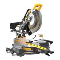
Transporting the Saw (Fig. A1, A2)
WARNING: To reduce the risk of serious personal injury,
ALWAYS lock the rail lock knob, mitre lock handle, bevel lock handle,
lock down pin and fence adjustment knobs before transporting saw.
Never use guards for transporting or liftingup.
In order to conveniently carry the mitre saw, a carrying handle
3
has been
included on the top of the sawarm.
• To transport the saw, lower the head and depress the lock down
pin
11
.
• Lock the rail lock knob with the saw head in the front position, lock the
mitre arm in the full left mitre angle, slide the fence
13
completely
inward and lock the bevel lock knob
33
with the saw head in the
vertical position to make the tool as compact aspossible.
• Always use the carrying handle
3
or the base extensions
15
.
Features and Controls
WARNING: To reduce the risk of serious personal injury, turn
tool off and disconnect battery pack before making any
adjustments or removing/installing attachments or accessories.
An accidental start-up can causeinjury..
Mitre Control (Fig.A2, I)
The mitre lock handle
21
and mitre latch button
22
allow you to mitre
your saw to 60° right and 50° left. To mitre the saw, lift the mitre lock
handle, push the mitre latch button and set the mitre angle desired on the
mitre scale
19
. Push down on the mitre lock handle to lock the mitreangle.
Override the mitre latch button by unlocking the mitre lock knob and
pushing the mitre detent override
38
downward. To exit the override, push
the mitre detent overrideupward.
Bevel Lock Knob (Fig. A2)
The bevel lock allows you to bevel the saw 49° left or right. To adjust the
bevel setting, turn the bevel lock knob
33
counterclockwise. The saw head
bevels easily to the left or to the right once the 0° bevel override knob is
pulled. To tighten, turn the bevel lock knobclockwise.
0° Bevel Override (Fig. A2)
The 0° bevel stop
34
override allows you to bevel the saw to the right past
the 0°mark.
When engaged, the saw will automatically stop at 0° when brought up
from the left. To temporarily move past 0° to the right, pull the bevel lock
knob
33
. Once the knob is released, the override will be reengaged. The
bevel lock knob can be locked out by twisting the knob 180°.
When at 0°, the override locks in place. To operate the override, bevel the
saw slightly to theleft.
45° Bevel Stop Override (Fig.J)
There are two bevel stop override levers, one on each side of the saw.
To bevel the saw, left or right, past 45°, push the 45° bevel override
lever
55
rearward. When in the rearward position, the saw can bevel past
these stops. When the 45° stops are needed, pull the 45° bevel override
leverforward.
Crown Bevel Pawls (Fig.J)
When cutting crown molding laying flat, your saw is equipped to accurately
and rapidly set a crown stop, left or right (refer to Instructions for Cutting
Crown Molding Laying Flat and Using the Compound Features)
The crown bevel pawl
57
can be rotated to contact the crown
adjustmentscrew.
 Loading...