25
ENGLISH
Three-phase machines
Please ensure the cable is provided with CEE 16A industrial plug/coupler 5 poles (neutral must
be connected) according to IEC60309.
Voltage Drops
Inrush currents cause short-time voltage drops. Under unfavourable power supply conditions,
other equipment may beaffected.
If the system impedance of the power supply is lower than 0.25 Ω, disturbances are unlikely
tooccur.
Sockets used for these machines shall be fused with 16 Amperes cut-out with an
inertcharacteristic.
Package Contents
The package contains:
1 Partly assembled radial arm saw
2 Table strips (1 right,1 left)
2 Fences (1 right, 1 left)
2 Table extensions (1 right, 1 left)
1 Dust shroud
1 Box containing:
1 legstand (4 legs, 4 traverse rails, 24 M8 x 16 bolts, 24 M8 nuts and 48 D8 flat washers)
1 Skinpack containing:
1 spanner 10/13 mm
1 spanner 22 mm
1 socket wrench 13 mm
5 hex keys (one 3, 4, 5 mm) (two 6 mm)
1 height adjustment crank
1 M4.2 x 16 cross head screw
4 table extension supports
19 M8 x 25 bolts
19 D8 flat washers
19 M8 nuts
1 rubber insert
6 wood inserts
3 M8 x 16 screws
3 D8 washers
1 Instruction manual
• Check for damage to the tool, parts or accessories which may have occurred duringtransport.
• Take the time to thoroughly read and understand this manual prior tooperation.
Markings on Tool
The following pictograms are shown on the tool:
Read instruction manual beforeuse.
Wear earprotection.
Wear eyeprotection.
When the power cord is damaged disconnect the plug from the power
sourceimmediately.
Always disconnect the plug before making any adjustments or perform service/
maintenance.
Date Code Position (Fig.A)
The date code
63
, which also includes the year of manufacture, is printed into thehousing.
Example:
2020 XX XX
Year of Manufacture
Description (Fig. A)
WARNING: Never modify the power tool or any part of it. Damage or personal injury
couldresult.
1
On/off switch
2
Handle
3
Front guard
4
Lower guard
5
Fixed table top
6
Traverse rails
7
Leg
8
Left fence (small)
9
Right fence (large)
10
Dust shroud
11
Mitre latch lever
12
Mitre clamp lever
13
Height adjustment crank
14
Radial arm
15
End-cap
16
Cable
17
Dust outlet
18
Yoke assembly
19
Motor
20
Left table strip
21
Right table strip
22
Left table extension
23
Right table extension
24
Bevel scale
25
Roller head assembly
26
No-volt release switch
27
Electronic control box
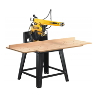
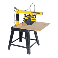
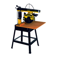
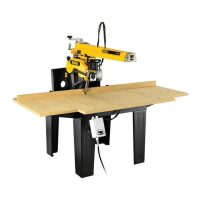
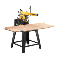
Intended Use
The radial arm saw has been designed for professional woodworking. This high precision
machine can be easily and quickly set to crosscut, bevel, mitre. For optimum safety, all major
controls have both a latch and a locking device. Also refer to the quick reference chart at the
end of the section. This saw is designed for use with a 300 mm diameter carbide tipblade.
DO NOT use under wet conditions or in the presence of flammable liquids orgases.
The radial arm saw is a professional powertool.
DO NOT let children come into contact with the tool. Supervision is required when
inexperienced operators use thistool.
• Young children and the infirm. This appliance is not intended for use by young children
or infirm persons withoutsupervision.
• This product is not intended for use by persons (including children) suffering from
diminished physical, sensory or mental abilities; lack of experience, knowledge or skills
unless they are supervised by a person responsible for their safety. Children should never
be left alone with thisproduct.
ASSEMBLY AND ADJUSTMENTS
WARNING: To reduce the risk of serious personal injury, turn tool off and
disconnect tool from power source before making any adjustments or removing/
installing attachments or accessories. Be sure the trigger switch is in the OFF position.
An accidental start-up can causeinjury.
WARNING: For optimum performance of your saw, it is of vital importance to follow the
procedures in the paragraphsbelow.
Set Up
Mounting the Height Adjustment Crank (Fig.A,B)
1. Apply the height adjustment crank
13
with the cross head screw.
NOTE: Automatic return arm may need to be moved to allow heightadjustment.
2. Raise the height adjustment crank high enough to provide clearance for removal of various
elements under themotor.
Assembling the Legstand (Fig.A,C)
The legstand components and fasteners are packedseparately.
1. Remove all parts from thepackage.
2. Lock the arm using the mitre clamp lever
12
.
3. Tilt the machine carefully from the pallet until the rear of the column is resting on thefloor.
4. Place a piece of wood
29
under the edge of the table (Fig.C).
5. Assemble the legs
7
as shown using the nuts, bolts and flat washersprovided.
NOTE: Do nottighten.
6. Mount the traverse rails
6
(Fig.C).
7. Firmly tighten allfasteners.
8. Tilt the machine to uprightposition.
IMPORTANT: Assistance may be required to lower and raise themachine.
Anchor the Machine (Fig.A,D)
WARNING: The machine must be level and stable at alltimes.
1. Move the machine to the desired location. See Transporting paragraph
underMaintenance.
2. Holes
28
in the legstands are provided to secure the machine to the floor. Using these
holes as templates, drill 10mm diameter holes with a minimum depth of 75mm.
3. Insert the anchor bolts
30
, with washer
31
and nut
32
partially threaded, through holes
in legs and into the floor. NOTE: Use FAZ ll 10/10 anchor bolts, soldseparately.
4. Tighten nut
32
.
Mounting the Automatic Return (Fig.A,E–J)
1. The automatic return comes partially assembled as shown in FigureE.
2. Partially unscrew automatic return retaining screw
33
with 6 mm hex key to allow for
rotation of automatic return system (Fig.F).
3. Unlock and move the head (Fig.G).
4. Rotate the automatic return. Insert the second screw
34
. NOTE: Do not tighten (Fig.H).
5. Set the automatic return, checking correct alignment with the roller head
25
(Fig.A,I).
6. The yoke travel stop must be adjusted so the yoke assembly bearings will not hit the rear
limit of the bearing tracks. Adjust the travel stop
35
until the rubber stop
36
butts against
the back of the riplock housing (Fig.J).
WARNING: The head must always be locked in the restposition.
7. Tighten allscrews.
Consult your dealer for further information on the appropriateaccessories.
Mounting the table extension (Fig.A,K–R)
1. Mount two of the table extension supports
37
to each side of the fixed table top
5
using
the M8 x 25 bolts (Fig.K).
2. Place a table extension
22
,
23
on the table extension support (Fig.L). Repeat with the
other tableextension.
3. Check that the table extensions are flush with the fixed table top and securely hand
tighten thebolts.
 Loading...