26
ENGLISH
WARNING: The table extensions and the fixed table top MUST beflush.
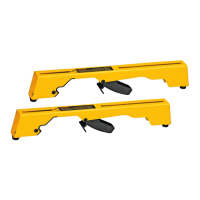
4. Insert 3 dowels into the small, left fence
8
and 3 dowels into the larger right fence
9
(Fig.A,M).
5. Align the left fence dowels with the left side holes in the fixed table top and firmly press
together (Fig.N).
6. Repeat with the rightfence.
7. Align the back, left table strip
20
with the left fence dowels and firmly press together
(Fig.O). Tighten the table clamp
38
with socket wrench (Fig.P).
8. Insert a M8 x 25 screw and D8 washer into the back, left table strip and securely tighten
(Fig.Q,R).
9. Repeat for back right tablestrip.
Mounting Dust Shroud (Fig.S,T)
1. Fit the dust port in position back to the columnbase.
2. Insert 3 M8 x 16 screws and D8 washers into the dust port and baseholes.
3. Tighten all with 3 M8 nuts using 13 mm socket wrench and open keyspanner.
Mounting the Cable Support (Fig.U,V)
1. Remove the cross head screw
39
.
2. Mount the cable support
40
and refit the cross headscrew.
3. Remove the cable clamps
41
located on the arm and reattach holding the cable inplace.
WARNING: Allow for the arm movement in horizontal and verticaldirection.
Mounting the Electronic Control Box (Fig.W)
Wired into the mains cable is the electronic control box
27
containing the no-volt release
switch
26
, the braking device and the motor overload protector with automaticreset.
1. Remove the nuts from the screws
42
protruding out of the rear of the box
27
.
2. Hold the box against the rear of the table frame to the left of the column base and insert
the screws into the correspondingholes.
3. Replace the nuts onto the end of the screws and tightenthem.
Mounting the Saw Blade (Fig.X–GG)
WARNING: To reduce the risk of injury, wear gloves when handling the sawblade.
1. Ensure that the arm position is at 0˚ and raise the arm
14
to the upper position (Fig.X).
2. Place one 6 mm hex key into the motor spindle and the other 6mm hex key on the blade
screw (Fig.Y), turn the blade screw clockwise to remove the blade screw
43
and external
flange
44
(Fig.Z).
3. Remove the blade from the spindle and fit the blade in the slot
45
of the table fence. The
teeth blade MUST NOT come into contact the spindle (Fig.AA,BB).
4. Unlock the head and move the head forward until the blade can be removed from the
slot
45
. Place the new blade
46
into the slot
45
and move the head slowly into the rest
(locked) position assuring that the teeth of the blade does not come into contact with the
spindle (Fig.CC–EE).
5. Place the new blade onto the internal flange
47
. Place the external flange
44
on the
spindle (Fig. FF). Place one 6 mm hex key into the motor spindle and the other 6mm hex
key on the blade screw, tighten the blade screw and external flange (Fig.Y).
NOTE: Lift the lower guard and slowly turn the blade to make sure the blade moves freely
without any side to sidemovement.
6. The head is ready for cutting (Fig. GG).
WARNING: The teeth of a new blade are very sharp and can bedangerous.
WARNING: The direction of rotation is indicated by the arrow on themotor.
WARNING: Make sure that the washer of the arbour nut is against the outerflange.
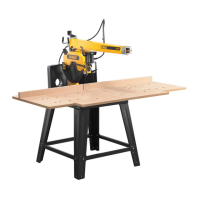
Checking that the Arm is Parallel to the Table Top (Fig.A, HH)
1. Lower the blade
46
until it only just touches the fixed table top
5
.
2. Release the mitre latch lever
11
and the mitre clamp lever
12
.
3. Extend the blade forward past the fence then swing arm so that the blade skims the table
top across itswidth.
4. Repeat this procedure with the blade in rear position and adjust the rear bolt ifrequired.
Checking that the Blade is Perpendicular to the Table Top (Fig.A, II–KK)
1. Bring the arm
14
back to centralposition.
2. Place a steel square
48
against the blade body (Fig. II).
3. If adjustment is required, proceed as follows:
a. Remove the bevel pointer disk
50
by loosening the two screws
51
(Fig.JJ).
b. Loosen all three hex screws that will be exposed in this way (Fig. KK).
c. Place a hex key in the motor arbour and tap until the blade is flat against thesquare.
4. Firmly tighten allfasteners.
WARNING: It is particularly important to tighten the central hexscrew.
5. Replace the bevel pointer disk
50
aligning the pointer
49
at 0˚.
Checking that the Crosscut Travel is Perpendicular to the Fence
(Fig.LL–PP)
1. Extend the blade in front of the fence (Fig. LL).
2. Place a square
48
on a piece of board and against the fence and just touching the blade
asshown.
3. Pull the blade towards you to check that the blade traverses parallel to thesquare.
4. If adjustment is required, proceed as follows:
a. With the mitre latch lever
11
engaged in 0° position, release the mitre clamp lever
12
as shown in FigureMM.
b. Loosen the locknuts
52
on each side of the arm
14
, shown in FigureNN.
5. To adjust the arm
14
to the left, loosen the stud
53
on the right-hand side of the arm
and tighten the opposite stud (Fig. OO).
6. To adjust the arm
14
to the right, loosen the stud
53
on the left-hand side of the arm
and tighten the oppositestud.
7. Proceed in small steps and check the adjustment after each step with the
levers
11
,
12
engaged.
WARNING: Do not overtighten thestuds.
8. Tighten the locknuts
52
.
9. Adjust the pointer
54
on the mitre scale
55
so that it registers 0° (Fig. PP).
Blade Guard Assembly (Fig. QQ)
The blade guard is a multifunctional assembly which offers the following safety features:
- Front guard
3
and spring-held rear guard
4
for full bladeprotection.
- Dust extraction adapter
57
.
- Adjustable finger guard
58
for use when cross-cutting.
Bevel Scale (Fig. RR)
Check that the bevel scale
24
reads 0˚ when positioned for a verticalcut.
If required, loosen the screws
51
and adjust the pointer to 0˚.
Mitre Scale (Fig. PP)
Check that the mitre scale
55
reads 0˚ when positioned for a verticalcut.
Adjust the pointer
54
to register 0˚ using the screw
56
.
The arm has preset positions at 45˚ left and right and at 0˚.
OPERATION
Instructions for Use
WARNING: Always observe the safety instructions and applicableregulations.
• Ensure the material to be sawn is firmly secured inplace.
• Apply only a gentle pressure to the tool and do not exert side pressure on the
sawblade.
• Avoidoverloading.
WARNING:
• Install the appropriate saw blade. Do not use excessively worn blades. The maximum
rotation speed of the tool must not exceed that of the sawblade.
• Do not attempt to cut excessively smallpieces.
• Allow the blade to cut freely. Do notforce.
• Allow the motor to reach full speed beforecutting.
• Make sure all locking knobs and clamp handles aretight.
• Never run the machine without the guards inplace.
• Never lift the machine by the tabletop.
• Always check that there is a suitable slot in the tabletop.
• Always refer to Figure UU to check the fence position andtype.
The attention of UK users is drawn to the “woodworking machines regulations 1974” and any
subsequentamendments.
Switching On and Off (Fig.A)
The on/off switch of your radial arm saw offers multiple advantages:
- No-volt release function: should the power be shut off for some reason, the switch
has to be deliberatelyreactivated.
- Motor overload protection device: in case of motor overload, the power supply to
the motor will be cut off. If this happens, let the motor cool for 10 minutes and then
press the resetbutton.
- Braking system: after switching off, the braking system will stop the saw blade within
10seconds.
- The switch has hold-to-run functionsonly.
To switch the machine on, press the green actuator
1
in the handle
2
. When the actuator is
released the machine stopsautomatically.
Making a Trial Cut (Fig.A)
1. With the mitre latch lever
11
engaged, lock the mitre clamp lever
12
so that the blade is
positioned for a straight 0° cross-cut.
2. Lower the arm until the blade almost touches the tabletop.
3. Place the workpiece against the front of thefence.
4. Switch on and lower the arm to allow the blade to cut a shallow groove in the
tablesurface.
5. Pull the blade towards you so that it cuts a vertical slot in the wooden fence and through
theworkpiece.
6. Return the blade back to rest position and switchoff.
7. Check that the cut is a true 90° in all planes and adjust ifrequired.
 Loading...