9
ENGLISH
When cutting a board between 3-5/8" (91 mm) and 5-1/2" (140 mm), the roller on the tip of the
guard will hang up on the workpiece. If this occurs, simply place your right thumb on the upper
side of the guard and roll the guard up just enough to clear the workpiece, as shown in FigureL.
Once you have cleared the workpiece, you can release the guard and it will continue to open as
the cutprogresses.
When mitring to the right side of a base molding 3-5/8" (91 mm) standing vertically against the
fence as in FigureS, the saw can only cut through the board up to 1" (25.4 mm) from the end
of the board. Trying to cut more than an inch will cause the saw’s gear case to interfere with
the workpiece. If you want to cut base molding between 3-5/8" (91 mm) and 5-1/2" (140 mm)
vertically follow the directions on thispage.
Cutting Base Molding up to 1" (25.4 mm) Thick by 3-5/8"–5-1/2"
(91 mm–140 mm) Wide Vertically Against the Fence
Position molding as shown in FigureS.
All cuts made with the back of the molding against the fence
Inside corner Outside corner
Left side*
1. Position molding with bottom of
molding against the base of the saw
2. Mitre left 45°
3. Save left side of cut
1. Position molding with bottom of
molding against the base of the saw
2. Mitre right 45°
3. Save left side of cut
Right side
1. Position molding with bottom of the
molding resting on the base of the saw
2. Mitre right 45°
3. Save right side of cut
1. Position molding with bottom of the
molding against the base of the saw
2. Mitre left 45°
3. Save right side of cut
* NOTE: If the cut must be made somewhere other than 1" (25.4 mm) from the end of the molding:
cut off the molding at 90° approx. 1" (25.4 mm) longer than your final length then make the mitre
cut as described above.
Cutting Base Molding up to 1.8" (45 mm) Thick by up to 7-11/16"
(195.6 mm) Wide Laying Flat and Using the Bevel Feature
All cuts made with the saw set at 45° bevel and 0mitre.
All cuts made with back of molding laying flat on thesaw.
Inside corner Outside corner
Left side
1. Position molding with top of molding
against the fence
2. Save left side of cut
1. Position molding with bottom of the
molding against the fence
2. Save right side of cut
Right side
1. Position molding with bottom of the
molding against the fence
2. Save right side of cut
1. Position molding with top of molding
against the fence
2. Save right side of cut
Cutting Crown Molding
Your mitre saw is better suited to the task of cutting crown molding than any tool made. In order
to fit properly, crown molding must be compound mitreed with extremeaccuracy.
The two flat surfaces on a given piece of crown molding are at angles that, when added together,
equal exactly 90°. Most, but not all, crown molding has a top rear angle (the section that fits flat
against the ceiling) of 52° and a bottom rear angle (the part that fits flat against the wall) of38°.
Your mitre saw has special pre-set mitre latch points at 31.6° left for cutting crown molding at the
proper angle and bevel stop pawl at 33.9° left. There is also a mark on the bevel scale at 33.9°.
The Bevel Setting/Type of Cut chart gives the proper settings for cutting crown molding. (The
numbers for the mitre and bevel settings are very precise and are not easy to accurately set on
your saw.) Since most rooms do not have angles of precisely 90°, you will have to fine tune your
settingsanyway.
PRETESTING WITH SCRAP MATERIAL IS EXTREMELY IMPORTANT!
Instructions for Cutting Crown Molding Laying Flat and Using
the Compound Features (Fig. A, T)
1. Molding laying with broad back surface down flat on saw table
34
(Fig.T).
Fig. T
10
34
2. The settings below are for All Standard (U.S.) crown molding with 52° and 38°angles.
BEVEL SETTING TYPE OF CUT
33.9°
LEFT SIDE, INSIDE CORNER
1. Top of molding against fence
2. Mitre table set right 31.6°
3. Save left end of cut
33.9°
RIGHT SIDE, INSIDE CORNER
1. Bottom of molding against fence
2. Mitre table set left 31.6°
3. Save left end of cut
33.9°
LEFT SIDE, OUTSIDE CORNER
1. Bottom of molding against fence
2. Mitre table set left 31.6°
3. Save right end of cut
33.9°
RIGHT SIDE, OUTSIDE CORNER
1. Top of molding against fence
2. Mitre table set right 31.6°
3. Save right end of cut
When setting bevel and mitre angles for all compound mitres, remember that:
The angles presented for crown moldings are very precise and difficult to set exactly. Since they
can easily shift slightly and very few rooms have exactly square corners, all settings should be
tested on scrapmolding.
PRETESTING WITH SCRAP MATERIAL IS EXTREMELY IMPORTANT!
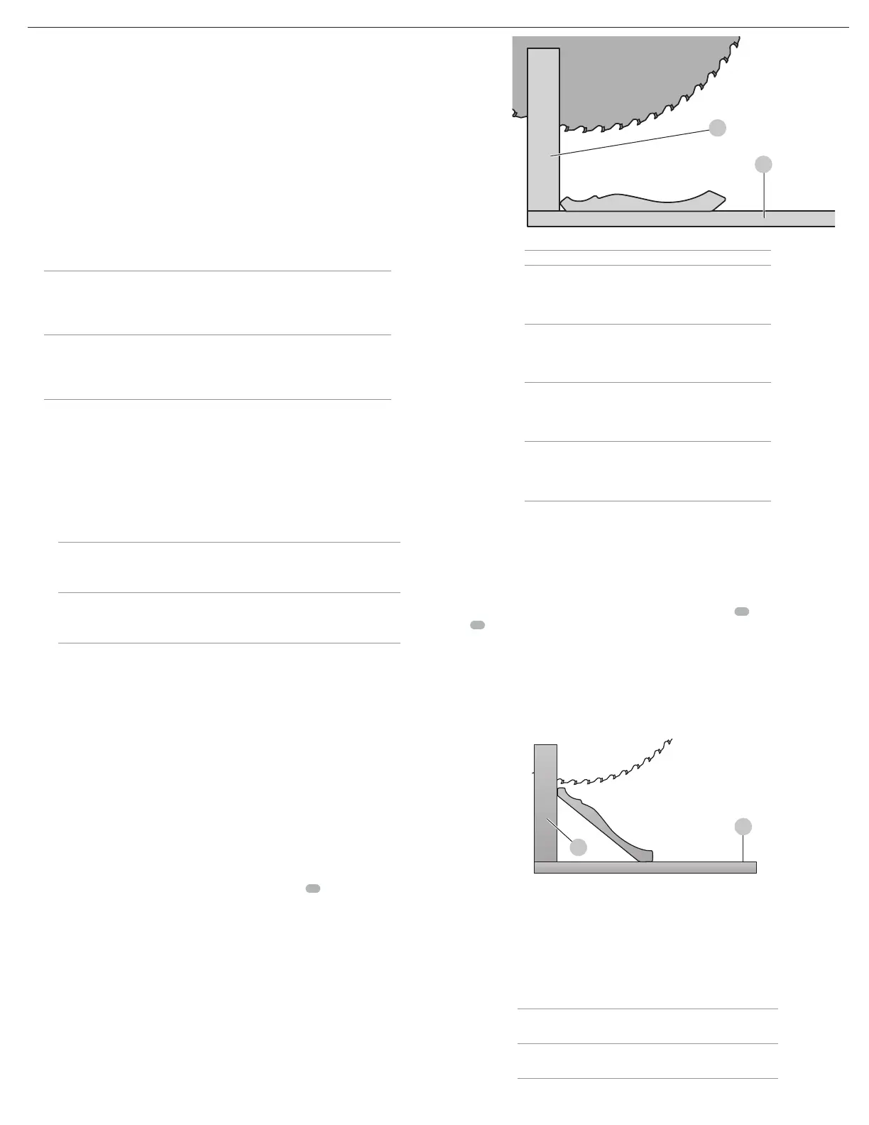
Alternative Method for Cutting Crown Molding (Fig. U)
Place the molding on the table at an angle between the sliding fence
10
and the saw
table
34
, as shown in FigureU. Use of the crown molding fence accessory (DW7084) is highly
recommended because of its degree of accuracy and convenience. The crown molding fence
accessory is available for purchase from your localdealer.
The advantage to cutting crown molding using this method is that no bevel cut is required.
Minute changes in the mitre angle can be made without affecting the bevel angle. This way,
when corners other than 90° are encountered, the saw can be quickly and easily adjusted for
them. Use the crown molding fence accessory to maintain the angle at which the molding will
be on thewall.
Fig. U
34
10
Instructions for Cutting Crown Molding Angled Between the
Fence and Base of the Saw for All Cuts
1. Angle the molding so the bottom of the molding (part which goes against the wall when
installed) is against the fence and the top of the molding is resting on the base of the saw, as
shown in FigureU.
2. The angled “flats” on the back of the molding must rest squarely on the fence and base of
thesaw.
Inside corner Outside corner
Left side
1. Mitre right 45°
2. Save right side of cut
1. Mitre left 45°
2. Save right side of cut
Right side
1. Mitre left 45°
2. Save left side of cut
1. Mitre right 45°
2. Save left side of cut

 Loading...