14
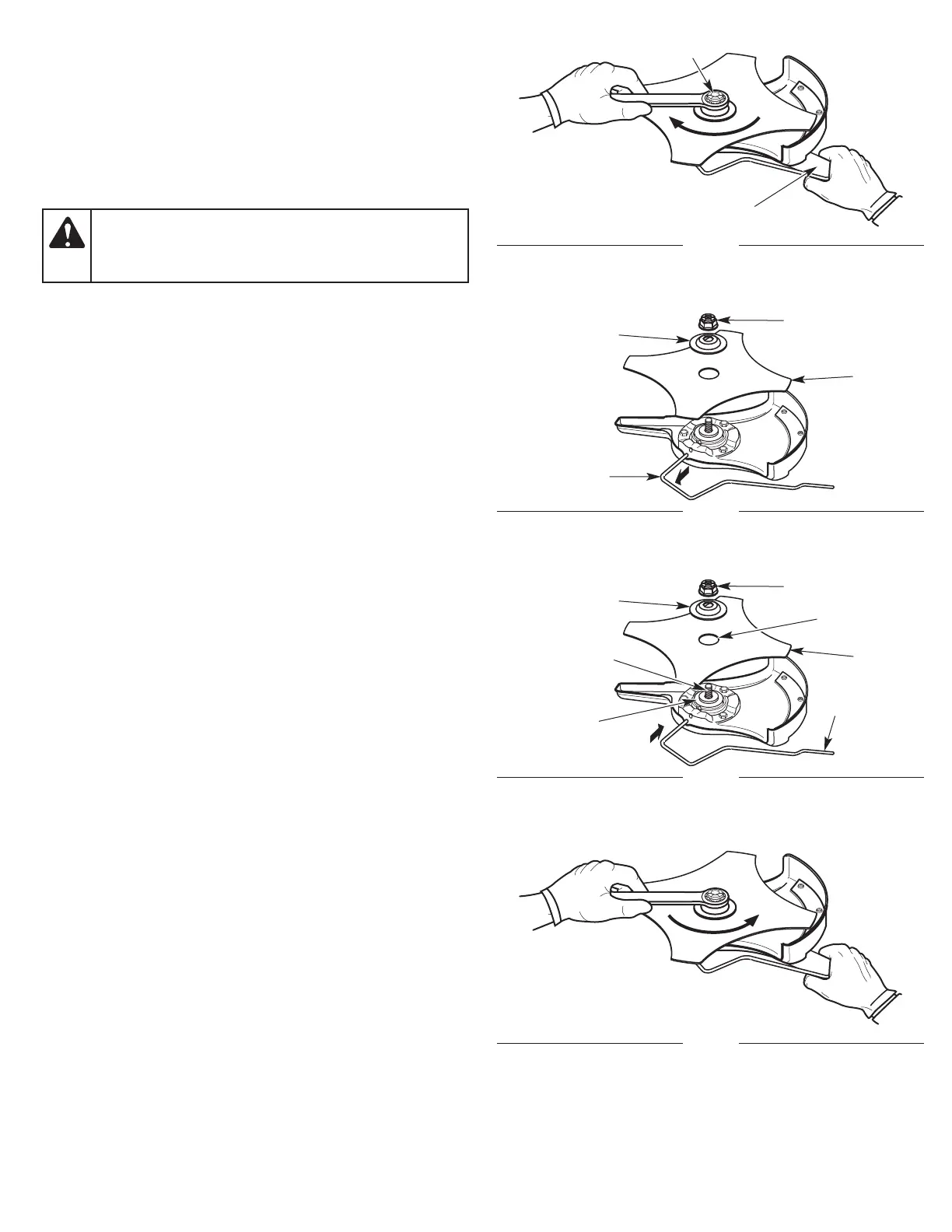
Installing the Blade
1. Rotate the output shaft bushing until the shaft bushing hole
aligns with the locking rod slot (Fig. 14).
2. Insert the locking rod through the locking rod slot and into the
shaft bushing hole (Fig. 14).
3. Hold the locking rod in place by grasping the other end against
the shaft housing (Fig. 15).
4. While holding the locking rod in place, put the blade on the
output shaft bushing (Fig. 17).
5. Place the blade retainer on the output shaft with the flat surface
against the blade (Fig. 17).
6. Screw the nut onto the output shaft (Fig. 17).
7. Tighten the nut counterclockwise with a wrench (Fig. 18):
• If using a torque wrench, torque to: 325 - 335 in•lb, 27 - 28
ft.•lb, 37 - 38 N•m.
• If using a closed-end or socket wrench, turn the nut until the
blade retainer is snug against the blade. Make sure the blade
is installed correctly, then rotate the nut an additional 1/4 to
1/2 turn counterclockwise.
8. Remove the locking rod.
WARNING:
To avoid serious personal injury, make sure
that the pilot hole on the blade is sitting flat against the
output shaft bushing (Fig. 17). The unit will vibrate and the
blade may fly off if the blade is not centered.
Fig. 16
Blade Retainer
Nut
Blade
Locking Rod
Fig. 15
Shaft Housing
Nut
Fig. 17
Blade Retainer
Nut
Blade
Output Shaft
Bushing
Locking Rod
Pilot Hole
Fig. 18
Output Shaft
 Loading...